tig welding settings chart pdf
TIG Welding Settings Chart PDF: A Comprehensive Guide
TIG welding, or GTAW, utilizes a tungsten electrode and inert gas․
Charts detailing amperage, voltage, and gas flow rates are crucial for optimal results․
PDF guides offer convenient access to these settings for various materials․
Understanding TIG Welding Basics
TIG (Tungsten Inert Gas) welding, also known as GTAW (Gas Tungsten Arc Welding), is a highly versatile process renowned for producing clean, precise welds․ Unlike other methods, TIG utilizes a non-consumable tungsten electrode to create the arc, shielding the weld pool with an inert gas – typically argon․ This shielding prevents atmospheric contamination, resulting in superior weld quality․
Understanding the core principles is vital before diving into specific settings․ The process relies on carefully controlling the heat input through amperage, while voltage influences the arc shape and penetration․ Filler metal, when needed, is fed manually, allowing for exceptional control over the weld bead․
TIG excels in welding a wide range of materials, including steel, stainless steel, aluminum, and even exotic alloys․ Accessing reliable TIG welding settings charts, often available as PDF documents, is crucial for beginners and experienced welders alike․ These charts provide a starting point, tailored to material type, thickness, and desired weld characteristics, ensuring consistent and high-quality results․
TIG Welding Process Overview
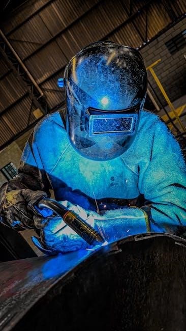
The TIG welding process initiates with a high-frequency arc established between a tungsten electrode and the workpiece․ This arc, shielded by an inert gas like argon, generates intense heat to melt the base metal and, if used, the filler metal․ The welder meticulously controls the heat input and filler metal addition, creating a clean and precise weld․
Key components include the power source, tungsten electrode, shielding gas supply, and welding torch․ The power source delivers the electrical current, while the tungsten electrode focuses the arc․ Shielding gas prevents oxidation and contamination․ Proper settings, often detailed in TIG welding settings charts (available as PDFs), are paramount․
TIG is often favored for its ability to create high-quality welds on various materials․ These charts typically outline amperage, voltage, gas flow rates, and electrode diameter recommendations based on material type and thickness․ Utilizing these resources ensures optimal weld parameters, minimizing defects and maximizing weld integrity․ Mastering this process requires practice and a solid understanding of these fundamental principles․
TIG vs․ MIG/MAG Welding: Key Differences
TIG (Tungsten Inert Gas) welding, also known as GTAW, differs significantly from MIG/MAG (Metal Inert Gas/Metal Active Gas) welding․ TIG employs a non-consumable tungsten electrode, requiring manual filler metal addition, offering precise control․ MIG/MAG utilizes a continuously fed wire electrode, automating the process and increasing welding speed․
TIG excels in producing high-quality, aesthetically pleasing welds on a wider range of materials, including aluminum and stainless steel, often referencing detailed TIG welding settings charts – frequently found as PDF guides․ MIG/MAG is generally faster and more suitable for thicker materials and production environments․
Shielding gas also differs; TIG primarily uses inert gases like argon, while MIG/MAG can employ both inert and active gases․ Understanding these distinctions is crucial for selecting the appropriate process․ PDF resources detailing settings for each process help welders optimize parameters for specific applications, ensuring weld quality and efficiency․
Materials Suitable for TIG Welding
TIG (Tungsten Inert Gas) welding demonstrates exceptional versatility, effectively joining a broad spectrum of metals․ Stainless steel, frequently detailed in TIG welding settings charts available as PDF downloads, benefits from TIG’s precise control, minimizing distortion and oxidation․ Aluminum, requiring alternating current (AC), also thrives under the TIG process, with specific settings outlined in specialized guides․
Carbon steel, both low and high alloy, is readily welded using TIG, though careful parameter selection – often found in comprehensive PDF resources – is vital․ Exotic metals like titanium, magnesium, and nickel alloys also respond well to TIG, demanding meticulous technique and adherence to recommended settings․
The process’s ability to control heat input makes it ideal for thin materials, preventing burn-through․ Accessing detailed TIG welding settings charts in PDF format allows welders to tailor parameters to the specific alloy and thickness, ensuring optimal weld integrity and mechanical properties․
TIG Welding Equipment Essentials
Successful TIG (Tungsten Inert Gas) welding hinges on having the right equipment․ A quality TIG welding machine, often referenced in TIG welding settings chart PDF guides, is paramount, offering precise amperage control․ A TIG torch, available in air-cooled or water-cooled varieties, delivers the welding current and shielding gas․
A reliable shielding gas supply – typically argon or argon/helium mixtures – is crucial, with flow rates detailed in PDF setting charts․ Tungsten electrodes, selected based on the material being welded, are essential consumables․ A foot pedal provides amperage control during welding, enhancing precision․
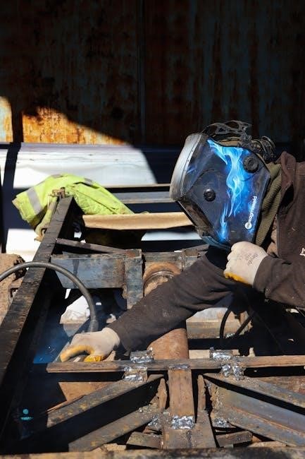
Safety gear, including a welding helmet with auto-darkening filter, gloves, and protective clothing, is non-negotiable․ Accessing TIG welding settings chart PDF resources often highlights the importance of proper equipment setup for achieving optimal weld quality and safety․ Proper grounding is also vital for a stable arc․
Tungsten Electrode Types and Selection
Choosing the correct tungsten electrode is vital for successful TIG welding, and TIG welding settings chart PDF guides often specify electrode types for different materials․ Tungsten electrodes are categorized by their composition, influencing arc characteristics and performance․
Pure tungsten is suitable for AC welding of aluminum, while 2% thoriated tungsten offers good arc starting and stability for DC welding of steel and stainless steel․ However, due to radioactivity, its use is declining․ Ceriated tungsten is a popular alternative, providing excellent arc starting and stability with lower radioactivity․
Lanthanated tungsten offers similar benefits to ceriated tungsten and performs well across a wider range of applications․ Electrode diameter impacts amperage capacity; PDF charts detail appropriate sizes․ Proper electrode preparation – tapering and grinding – is crucial for arc stability and weld quality․ Selecting the right tungsten, as indicated in setting charts, ensures optimal results․
Shielding Gas Choices for TIG Welding
Shielding gas plays a critical role in TIG welding, protecting the weld pool from atmospheric contamination․ TIG welding settings chart PDF resources frequently detail gas selection based on the material being welded․ Argon is the most common shielding gas, suitable for a wide range of materials, including steel, stainless steel, and aluminum․
However, for aluminum, adding helium to argon (typically 75% argon/25% helium) increases heat input and improves weld penetration․ Helium is also used for thicker materials requiring higher heat; Argon-hydrogen mixtures are sometimes used for stainless steel, enhancing cleaning action and weld quality․
Gas flow rate, specified in PDF charts, is crucial; too low leads to contamination, while too high can cause turbulence․ Proper gas coverage ensures a clean, defect-free weld; The choice of shielding gas significantly impacts arc characteristics, weld penetration, and overall weld quality, making chart guidance essential․
AC vs․ DC TIG Welding: When to Use Which
TIG welding settings chart PDF guides often delineate between AC (Alternating Current) and DC (Direct Current) processes․ DCEN (DC Electrode Negative), commonly used for steel and stainless steel, concentrates heat on the workpiece, providing deep penetration․ PDF charts will specify amperage ranges for various thicknesses using DCEN․
AC welding is primarily used for aluminum and magnesium․ The alternating current provides a “cleaning action,” breaking up the oxide layer that forms on these metals․ This cleaning action is vital for achieving sound welds․ The frequency of the AC cycle, detailed in some advanced charts, influences arc characteristics and penetration․
Choosing the correct polarity is crucial․ DC is generally preferred for materials that don’t readily form oxides, while AC excels where oxide removal is necessary․ Understanding these differences, and referencing a comprehensive TIG welding settings chart PDF, ensures optimal weld quality and process efficiency․
TIG Welding Settings Chart: Steel
A reliable TIG welding settings chart PDF for steel typically categorizes settings by material thickness․ For mild steel, charts often recommend DCEN (Direct Current Electrode Negative) polarity․ Amperage ranges vary significantly – for example, 1/8” steel might require 70-90 amps, while 1/4” could need 110-130 amps․ Voltage is usually set between 10-15 volts, adjusted based on arc length and travel speed․
Stainless steel settings, found within the same PDF, often utilize similar amperage ranges but may benefit from slightly lower heat input to prevent distortion or burn-through․ Argon is the standard shielding gas, with flow rates between 15-20 CFH (cubic feet per hour)․ Tungsten selection – typically 2% thoriated or ceriated – is also noted․
Detailed charts will also indicate appropriate travel speeds and electrode diameter․ Remember, these are starting points; adjustments are often needed based on joint preparation and welder technique․ Always consult a comprehensive TIG welding settings chart PDF for specific alloy recommendations․
TIG Welding Settings Chart: Stainless Steel
TIG welding settings chart PDFs for stainless steel emphasize minimizing heat input to preserve corrosion resistance․ DCEN (Direct Current Electrode Negative) polarity is generally preferred․ Amperage settings depend on thickness; 16-gauge (1․6mm) stainless might require 60-80 amps, while 1/8” (3․2mm) could need 90-110 amps․ Voltage typically ranges from 10-14 volts, fine-tuned for arc stability․
Argon is the dominant shielding gas, with flow rates of 15-20 CFH ensuring adequate protection․ Tungsten selection is critical; 2% thoriated, ceriated, or lanthanated electrodes are common choices․ Charts often specify electrode diameter based on amperage․ Pre-flow and post-flow gas settings are also detailed, usually around 2-5 seconds each․
A good TIG welding settings chart PDF will differentiate between austenitic (304, 316) and ferritic stainless steels, as they require slightly different parameters․ Remember to prioritize cleanliness and proper joint preparation for optimal results․ Always refer to a detailed PDF for specific alloy guidance․
TIG Welding Settings Chart: Aluminum
TIG welding settings chart PDFs for aluminum necessitate AC (Alternating Current) polarity to break down the oxide layer․ Amperage is crucial; for 1/8” (3․2mm) aluminum, 80-120 amps is a typical starting point, adjusted based on alloy and joint design․ Voltage usually falls between 12-16 volts, aiming for a stable arc․ Frequency control, often found in advanced machines, influences arc width and penetration․
Pure argon is the primary shielding gas, with flow rates of 15-20 CFH․ However, helium-argon mixtures can enhance penetration for thicker sections․ Tungsten selection is vital; pure tungsten or 2% lanthanated electrodes are preferred․ Charts detail electrode diameter correlated to amperage․ Cleaning the aluminum with a stainless steel brush before welding is essential․
A comprehensive TIG welding settings chart PDF will specify settings for different aluminum alloys (5052, 6061, etc․)․ Pre-flow and post-flow gas settings are critical, often 5-10 seconds, due to aluminum’s high thermal conductivity․ Always consult a detailed PDF for optimal parameters․
Understanding Amperage Settings
TIG welding settings chart PDFs emphasize amperage as the primary heat input control․ Amperage dictates the arc’s intensity and penetration depth․ Lower amperage is suitable for thin materials, preventing burn-through, while higher amperage tackles thicker sections․ A PDF chart correlates material thickness to recommended amperage ranges, serving as a starting point․
Understanding the relationship between amperage and material is key․ Steel generally requires lower amperage than aluminum for the same thickness․ Charts often provide specific amperage guidelines for various steel alloys (mild steel, stainless steel) and aluminum grades․ Adjustments are necessary based on joint configuration (butt, lap, fillet) and welding position․
Proper amperage selection minimizes distortion and ensures a sound weld․ Too low, and you’ll experience poor fusion; too high, and you risk overheating and porosity․ A detailed TIG welding settings chart PDF will also indicate appropriate tungsten electrode sizes for specific amperage ranges, optimizing arc stability and weld quality․
Voltage Control in TIG Welding
While amperage is primary, voltage significantly influences arc shape, weld bead profile, and travel speed in TIG welding․ TIG welding settings chart PDFs often present voltage as a secondary parameter, typically ranging from 10-15 volts, but adjustable based on material and amperage․ Higher voltage creates a wider, flatter bead, ideal for filling gaps and achieving a broader weld pool․
Lower voltage results in a narrower, more focused arc, providing deeper penetration – beneficial for root passes or welding thicker materials․ Voltage control is often linked to amperage; increasing amperage usually necessitates a corresponding voltage increase to maintain arc stability․ Charts may illustrate optimal voltage ranges for given amperage settings and material types․
Modern TIG machines offer adjustable AC balance, impacting voltage characteristics, particularly when welding aluminum․ A PDF guide will explain how to fine-tune voltage for specific applications, ensuring proper cleaning action and weld bead appearance․ Mastering voltage control, alongside amperage, is crucial for achieving high-quality, consistent welds․
Pulse TIG Welding: Benefits and Settings
Pulse TIG welding offers superior control over heat input, minimizing distortion and improving weld quality, especially on thin materials․ TIG welding settings chart PDFs dedicated to pulse welding detail parameters like peak current, background current, pulse frequency, and pulse duty cycle․ Peak current determines the weld penetration, while background current maintains the arc without adding significant heat․
Pulse frequency (pulses per second) influences weld bead appearance and heat distribution; higher frequencies create a narrower bead with less heat input․ Duty cycle, the percentage of time at peak current, controls the overall heat delivered․ Charts often provide starting points for these settings based on material type and thickness․
Benefits include reduced warping, improved control on corners and joints, and enhanced aesthetic appeal․ Advanced TIG machines allow for waveform customization, further refining pulse parameters․ A comprehensive PDF guide will illustrate how to adjust these settings to achieve optimal results for various applications, from stainless steel to aluminum․
Foot Pedal Control and Techniques
Foot pedal control is fundamental to skilled TIG welding, allowing dynamic amperage adjustment during the welding process․ TIG welding settings chart PDFs often provide guidance on correlating foot pedal pressure to amperage output for specific materials and thicknesses․ Mastering foot pedal technique enables precise heat control, crucial for achieving clean, consistent welds․
Techniques include ‘tacking’ with low amperage, gradually increasing it for penetration, and reducing it again for finishing passes․ Smooth, controlled pedal movements are essential to avoid erratic arc behavior and porosity․ Charts may suggest initial pedal settings for different joint configurations and welding positions․
Advanced techniques involve ‘pulse’ control via the foot pedal, modulating the current for enhanced control․ Understanding the relationship between pedal pressure, amperage, and arc characteristics is key․ A detailed PDF resource will demonstrate proper foot pedal operation, troubleshooting common issues, and optimizing settings for various welding scenarios, improving weld quality and efficiency․
Pre-Flow and Post-Flow Gas Settings
Pre-flow and post-flow gas settings are critical for shielding the weld pool and preventing oxidation during TIG welding․ TIG welding settings chart PDFs typically detail recommended gas flow rates (measured in cubic feet per hour ─ CFH or liters per minute — LPM) for various materials and thicknesses․ Pre-flow establishes a protective atmosphere before the arc starts, while post-flow continues shielding after the arc stops․
Insufficient pre-flow can lead to contamination, while inadequate post-flow can cause oxidation as the weld cools․ Charts often specify settings based on gas type (argon, helium, or mixtures) and nozzle size․ Optimal pre-flow is generally 1-3 seconds, and post-flow 5-10 seconds, but these values vary․
A comprehensive PDF guide will explain how to adjust these settings based on welding environment (drafts), joint geometry, and material reactivity․ Correct gas shielding ensures high-quality, defect-free welds, and a detailed chart provides a starting point for fine-tuning these essential parameters․
Travel Speed and its Impact on Weld Quality
Travel speed significantly impacts weld penetration, bead width, and overall quality in TIG welding․ TIG welding settings chart PDFs often provide guidance on appropriate travel speeds correlated with amperage, material thickness, and joint design․ Too slow a speed results in excessive heat input, leading to a wide, potentially burned-through weld․ Conversely, a speed that’s too fast can cause insufficient penetration and a weak, inconsistent bead․
Charts typically don’t offer precise speeds, as this is highly dependent on welder skill and technique․ Instead, they provide amperage ranges and suggest observing the weld pool for proper fluidity and wetting․ Consistent travel speed is paramount; variations create uneven welds․
A good PDF resource will emphasize the importance of maintaining a steady hand and a rhythmic motion․ It will also explain how to visually assess weld quality – looking for proper fusion, consistent bead shape, and absence of defects – to adjust travel speed accordingly․ Mastering this balance is key to achieving strong, aesthetically pleasing welds․
Common TIG Welding Defects and Troubleshooting
TIG welding settings chart PDFs frequently include sections dedicated to identifying and resolving common defects․ Porosity, caused by contamination or insufficient shielding gas, is a frequent issue․ Troubleshooting involves ensuring clean base metal, proper gas coverage, and correct gas flow rates – all detailed in comprehensive charts․
Another common defect is tungsten inclusion, resulting from accidentally dipping the electrode into the weld pool․ Charts emphasize maintaining a proper arc length and avoiding contact․ Cracking can occur due to excessive heat input or improper material selection; PDF guides correlate settings to material types․
Lack of fusion, often stemming from insufficient amperage or travel speed, is addressed by referencing amperage charts based on material thickness․ A good resource will also cover burn-through, suggesting reduced amperage or increased travel speed․ Utilizing these charts systematically aids in diagnosing and correcting weld imperfections, improving overall weld quality․
Reading and Interpreting TIG Welding Charts
TIG welding settings chart PDFs are designed to be systematic guides, but understanding their layout is crucial․ Typically, charts are organized by material type – steel, stainless steel, aluminum – and thickness․ Amperage is the primary setting, often correlated to material thickness and joint configuration․
Voltage settings are usually presented as a range, requiring adjustment based on arc length and desired weld bead profile․ Gas flow rates, measured in cubic feet per hour (CFH), are critical for shielding; PDF charts specify optimal ranges․ Electrode diameter recommendations are also common, influencing arc characteristics․
Advanced charts may include pulse settings – peak amperage, background amperage, and pulse frequency – for refined heat control․ Interpreting these charts requires understanding the interplay between settings; a higher amperage necessitates increased gas flow․ Mastering chart reading minimizes trial-and-error, leading to consistent, high-quality welds․
Creating a Custom TIG Welding Settings Chart
While TIG welding settings chart PDFs provide excellent starting points, tailoring a chart to your specific equipment and applications is beneficial․ Begin by documenting settings for frequently welded materials and thicknesses․ Record amperage, voltage, gas flow rate, electrode type, and tungsten diameter․
Systematically test and refine these settings, noting the resulting weld quality – penetration, bead profile, and absence of defects․ A spreadsheet format is ideal for organization, allowing easy adjustments and comparisons․ Include columns for joint type (butt, lap, fillet) and welding position (flat, horizontal, vertical, overhead)․
Consider adding notes on specific challenges encountered and solutions implemented․ Regularly update your chart as you gain experience and refine your techniques․ A personalized chart, built from practical experience, will significantly improve welding consistency and efficiency, surpassing generic PDF guides․
Resources for TIG Welding Settings PDFs
Numerous online resources offer downloadable TIG welding settings chart PDFs․ Welding equipment manufacturers, like Miller and Lincoln Electric, frequently provide comprehensive guides specific to their machines․ These charts often detail settings for steel, stainless steel, and aluminum, covering various thicknesses and joint configurations․
Industry websites and forums dedicated to welding are also valuable sources․ Websites specializing in metal fabrication often host user-contributed charts and discussions regarding optimal settings․ Educational institutions offering welding programs may publish resources accessible to the public․
However, remember that these PDFs serve as starting points․ Material composition, gas purity, and individual welder technique influence optimal settings․ Always prioritize safety and practice proper welding procedures․ Cross-reference multiple sources and adapt settings based on your specific needs and observations․
Advanced TIG Welding Techniques
Beyond basic settings, mastering advanced TIG techniques refines weld quality․ Pulse TIG, controlled via settings on modern machines, minimizes heat input, crucial for thin materials and stainless steel․ Precise amperage control, often utilizing a foot pedal, allows dynamic adjustment during welding, adapting to changing conditions․
Autogenous TIG welding, joining materials without filler metal, demands precise heat control and clean material preparation․ Back-purging with argon, a setting influencing gas flow, protects the weld root from oxidation, vital for critical applications․
Understanding waveform control – square wave versus sine wave – impacts arc characteristics and penetration․ While TIG welding settings charts provide a foundation, experimentation and practice are key․ Advanced techniques require a deep understanding of the interplay between amperage, voltage, gas flow, and travel speed to achieve optimal results and consistent, high-quality welds․