Manuals

manual lavadora general electric modelos

General Electric offers a wide range of washing machine models designed for efficiency and durability. Their manuals provide essential installation, operation, and maintenance instructions, ensuring optimal performance and troubleshooting guidance. Available online, these guides help users maximize their appliance’s potential.

Overview of Popular GE Washing Machine Models

GE offers a variety of washing machine models, each designed to meet specific needs. Popular models include the GUD24GSSMWW, known for its advanced dispensing system and high-efficiency performance, and the GTW465ASNWW, which features a large capacity and intuitive controls. The LV1135 model is praised for its durability and reliable operation. Many GE models come with energy-saving technologies and multiple wash cycles, catering to both residential and commercial use. Manuals for these models are readily available online, providing detailed instructions for installation, operation, and troubleshooting. These models highlight GE’s commitment to innovation, efficiency, and user-friendly design, making them top choices for homeowners seeking dependable appliances.

Importance of Using the Correct Manual for Your Model

Using the correct manual for your GE washing machine model is crucial for proper installation, operation, and maintenance. Each model has unique features and requirements, and the manual provides specific instructions tailored to your appliance. Incorrect usage can lead to malfunctions, safety hazards, or voiding the warranty. Manuals are available online in multiple languages, including Spanish and English, ensuring accessibility for all users. They cover essential topics like detergent usage, cycle selection, and troubleshooting. Referencing the correct manual helps prevent errors, ensures optimal performance, and extends the lifespan of your washing machine. Always verify your model number to download the accurate guide for your specific appliance.

Installation and Setup Instructions

Proper installation of your GE washing machine is essential to prevent damage and ensure safety. Always follow model-specific instructions to avoid malfunctions and ensure efficient operation.

Step-by-Step Guide for Installing Your GE Washing Machine

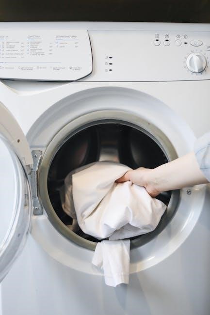
Unpack the washing machine and ensure all components are included. Inspect for damage and report any issues to avoid installation problems. Level the machine using adjustable feet to prevent vibration. Connect water supply lines to the correct hot and cold water inlets. Ensure electrical connections are secure and meet local codes. Install the drain hose properly, avoiding kinks or blockages. Test the machine by running a short cycle without detergent to check for leaks or noise. Refer to the manual for specific model requirements, such as additional accessories or settings. Proper installation ensures safety, efficiency, and optimal performance of your GE washing machine.

Connecting Electrical and Water Supply Lines

Connecting your GE washing machine requires careful attention to electrical and water supply lines. Ensure the washing machine is unplugged before starting. Connect the electrical cord to a properly grounded 120V outlet, avoiding extension cords. For water supply, attach the hot and cold water hoses to the respective inlet valves on the machine, ensuring they are securely tightened. Use Teflon tape to prevent leaks. If your home has high water pressure, consider installing a water hammer arrestor. Refer to your model’s manual for specific instructions, as some models may have additional requirements. Proper connections ensure safe and efficient operation of your washing machine.

Operating the Washing Machine

Operating your GE washing machine involves selecting the right wash cycle via the control panel, using HE detergent, and following guidelines for optimal cleaning efficiency.

Understanding Control Panels and Wash Cycles

GE washing machines feature intuitive control panels with options for selecting wash cycles, water temperature, and spin speed. Common cycles include Normal, Heavy Duty, and Delicate. The timer allows precise control over wash and rinse times. Specialized settings like Deep Fill and Sanitize ensure tailored cleaning for specific fabric types. Dispensers for detergent, bleach, and fabric softener are clearly labeled, guiding users to add the correct amounts. The control panel also provides status updates during operation. Referencing the manual ensures proper use of advanced features, optimizing cleaning efficiency and fabric care. Understanding these controls enhances user experience and prolongs appliance lifespan.

Using Detergent and Fabric Softener Dispensers

GE washing machines feature convenient detergent and fabric softener dispensers to streamline the laundry process. The detergent dispenser typically has three compartments: one for pre-wash, main wash, and fabric softener. For optimal performance, use high-efficiency (HE) detergent, as recommended in the manual. Avoid overfilling compartments, as this can lead to residue buildup. Fabric softener should be added to the designated dispenser, ensuring it’s released during the rinse cycle. Always refer to your model’s manual for specific instructions, as dispenser designs may vary. Proper use of these dispensers ensures effective cleaning, prevents clogging, and maintains your washer’s efficiency over time.

Maintenance and Troubleshooting

Regular maintenance ensures your GE washing machine runs efficiently. Clean filters, check for blockages, and run cleaning cycles. Troubleshooting common issues like error codes or leaks.

Cleaning the Washing Machine and Filters

Regular cleaning of your GE washing machine and its filters is essential for optimal performance. The filter, often located beneath the agitator or at the pump, should be cleaned periodically to remove debris. Run a cleaning cycle with a washer cleaner or vinegar to eliminate odors and residue. Check the detergent dispenser for buildup and wipe it clean. For models like the GUD24GSSMWW, ensure the chlorine compartment is emptied after use. Leave the lid open after cycles to dry the interior. Refer to your specific model’s manual for detailed instructions. Regular maintenance prevents mold growth and ensures fresh, clean laundry every time.

Common Issues and Solutions for GE Models

GE washing machines may encounter issues like clogged filters, detergent dispenser buildup, or error codes. For clogs, clean the filter regularly, especially after detecting debris. If the dispenser is clogged, soak it in warm water. Error codes often indicate specific problems, such as imbalanced loads or drainage issues. Models like the GUD24GSSMWW may show errors for oversize loads or poor ventilation. Regular cleaning cycles with vinegar or cleaning agents can prevent mold and odors. Always refer to your model’s manual for troubleshooting guidance. Ensuring proper maintenance and addressing issues promptly extends the appliance’s lifespan and performance. Check user manuals for detailed solutions tailored to your specific GE model.

Frequently Asked Questions

Frequently Asked Questions about GE washing machines include troubleshooting tips, detergent recommendations, and warranty details. Manuals and customer support are available online for assistance.

Energy Efficiency and HE Detergent Usage

General Electric washing machines are designed to be energy efficient, with many models earning the ENERGY STAR certification. Using HE (High Efficiency) detergent is recommended, as it produces fewer suds and is specifically designed for low-water washing machines. HE detergent helps maintain your washer’s performance and prevents residue buildup. ENERGY STAR certified models use less water and energy, reducing utility bills and environmental impact. Always check your manual for detergent recommendations, as using the wrong type can affect efficiency. Proper detergent usage ensures optimal cleaning and longevity of your GE washing machine.

Warranty and Customer Support Information

General Electric washing machines come with comprehensive warranties, typically covering parts and labor for up to one year, with extended options available. The motor often has a 10-year warranty. Customers can register their products online for warranty activation and access support resources. GE Appliances provides dedicated customer service through their website, phone, and live chat. Manuals and troubleshooting guides are readily available online to address common issues. For further assistance, users can contact GE’s support team or visit authorized service centers. Warranty details and support options ensure peace of mind and reliable service for GE washing machine owners.

GE washing machine manuals are essential for optimal use, offering detailed guides for installation, operation, and troubleshooting. Additional resources are available online, including FAQs, user forums, and direct customer support, ensuring comprehensive assistance for all models. Visit the official GE Appliances website for the latest manuals and support information.

Where to Find More Information and Manuals Online

General Electric washing machine manuals and additional resources are readily available online. Visit the official GE Appliances website for model-specific guides, troubleshooting tips, and warranty information. Third-party platforms like ManualsLib and ManualsOnline also host a wide range of GE washing machine manuals. For specific models, such as the GE GUD24GSSMWW or GE GTW465ASNWW, search the model number along with “manual” to find detailed instructions. Additionally, user forums and customer support pages provide helpful insights and answers to common questions. Ensure to download manuals from trusted sources to avoid misinformation.

Manuals

bestway pool pump instruction manual

Safety Instructions

Always follow safety guidelines to ensure safe operation. Avoid electrical hazards and keep children away from the pool when the pump is in use. Proper installation is crucial to prevent damage and ensure efficiency. Never operate the pump without proper assembly. Regular maintenance is essential for optimal performance and safety. Refer to the manual for detailed instructions and safety precautions to avoid accidents and prolong the product’s lifespan. Always handle electrical components with care and follow all warnings provided in the manual to ensure a safe and enjoyable experience with your Bestway pool pump. Safety first!

1.1 Important Safety Warnings

Do not submerge the pump in water or expose it to harsh weather conditions. Ensure all electrical connections are secure and meet local safety standards. Avoid overloading the pump, as this can cause permanent damage. Keep the area around the pump clean and clear of debris to maintain proper airflow and function. Never attempt to repair the pump while it is in operation. Always turn off the power before performing any maintenance or cleaning tasks. Follow all instructions carefully to prevent accidents and ensure the longevity of your Bestway pool pump. Your safety is our priority.

1.2 Precautions to Avoid Damage

Protect the pump from freezing temperatures, as this can cause internal damage. Do not use abrasive chemicals or cleaners, as they may damage the pump’s components. Always drain the pump and filter system before winter storage to prevent ice formation. Ensure the pump is installed on a level, stable surface to maintain balance and proper operation. Avoid using the pump in areas with standing water or poor ventilation. Regularly inspect the pump and filter for signs of wear or damage. By following these precautions, you can extend the life of your Bestway pool pump and ensure optimal performance.

Read the manual carefully before installing or operating the Bestway pool pump. Avoid electrical hazards by ensuring all connections are secure and dry. Keep children away from the pump and pool when in operation. Do not submerge the pump in water or expose it to harsh weather. Follow all safety guidelines to prevent accidents and ensure proper function. Your safety is a top priority.

Protect the pump from freezing temperatures, as this can cause internal damage. Ensure the correct voltage is used to avoid motor damage. Avoid using abrasive cleaners or chemicals, as they may damage components. Regularly inspect hoses and connections for wear or leaks. Drain the pump and filter during winter to prevent ice formation. Store the pump in a dry, protected area when not in use. Follow these precautions to maintain optimal performance and extend the lifespan of your Bestway pool pump. Proper care ensures durability.

Product Specifications

The Bestway pool pump features a powerful motor, delivering a maximum flow rate of 1000 gallons per hour. It includes a durable sand filter with a capacity of 15 kg, ensuring efficient water circulation and purification. Designed for compatibility with various Bestway pool models, this pump is built for reliability and optimal performance. Key specifications include: energy-efficient design, easy operation, and a robust construction for extended durability. Perfect for maintaining clean and safe pool water.

2.1 Technical Details of the Bestway Pool Pump

The Bestway pool pump features a high-performance motor with a flow rate of up to 1000 gallons per hour. It includes a durable sand filter system designed for efficient water circulation and purification. The pump is compact, lightweight, and built for long-lasting use with Bestway pool models. It operates at a low noise level and is energy-efficient. Dimensions: 15″ x 12″ x 22″. Includes: 32mm pool valve adapters for compatibility with various Bestway pool sizes. Maximum pressure: 12 bar. Power: 110-120V AC, 60Hz. Perfect for maintaining clean and safe pool water year-round.

2.2 Compatibility with Bestway Pool Models

This Bestway pool pump is designed to work seamlessly with various Bestway pool models, including rectangular and Fast Set inflatable pools. It is fully compatible with pools equipped with 32mm pool valves, ensuring easy installation and reliable performance. The pump is suitable for Bestway pool sizes ranging from small to large, making it a versatile option for different pool setups. Perfectly adapted for Bestway pools, it ensures optimal water circulation and filtration efficiency. Always check compatibility before purchase to ensure proper functionality with your specific pool model. Designed to enhance your Bestway pool experience.

Parts Reference Overview

This section provides a detailed list of all components included with your Bestway pool pump, such as the pump, filter, strainer basket, hoses, valves, and connectors. Refer to this guide to identify each part and ensure all items are included before assembly. If any parts are missing, contact Bestway Customer Service immediately. Accurate identification of components is essential for proper installation and operation. Organize all parts carefully to avoid loss or damage during setup. Understanding each part’s purpose will help you assemble and maintain your pool pump effectively. Everything you need for a successful setup is included in this comprehensive overview. Review this section thoroughly before proceeding with installation to ensure all components are accounted for and properly prepared. Your satisfaction is guaranteed with complete and accurate parts reference. Bestway ensures quality and completeness in every product. Enjoy a hassle-free experience with your Bestway pool pump. Happiness starts here with your new Bestway pool pump. Thank you for choosing Bestway. Happy swimming! 🏊♂️

3.1 List of Components Included

Your Bestway pool pump package includes the pump unit, sand filter, strainer basket, hoses, clamps, valves, and mounting hardware. Verify all items are present before starting assembly. If any parts are missing or damaged, contact Bestway Customer Service for assistance. Ensure all components are in good condition to guarantee proper function and safety. Store extra parts safely to avoid loss. Refer to this list during assembly to confirm each part is correctly identified and used. Complete your setup with confidence using the included components. Bestway provides everything needed for a seamless installation. Succeed with your Bestway pool pump setup. Enjoy your pool with peace of mind. Bestway cares about your satisfaction. Happy swimming! 🏊♀️

3.2 Understanding the Pump and Filter System

The pump circulates water through the filter, ensuring clean and safe swimming conditions. Understand how the pump and filter work together to maintain water clarity. Learn how to operate and maintain the system for optimal performance. Refer to this guide for detailed explanations of each component’s function. Know how to troubleshoot common issues to keep your pool running smoothly. Master the basics of pump and filter operation to enjoy your pool all season long. Bestway makes it easy to understand and maintain your pool system. Confidence comes with knowledge. Bestway is here to help. Happy swimming! 🏊♂️

Your Bestway pool pump package includes the pump unit, sand filter, strainer basket, hoses, clamps, valves, and mounting hardware. Additional accessories such as O-rings, gaskets, and connector fittings are also provided. Ensure all items are present before starting assembly. If any parts are missing, contact Bestway Customer Service for assistance. Refer to this list during assembly to confirm each part is correctly identified and used. Organize all components carefully to avoid loss or damage. Understanding each part’s purpose will help you assemble and maintain your pool pump effectively. Bestway ensures quality and completeness in every product. Enjoy a hassle-free experience with your Bestway pool pump. Your satisfaction is guaranteed with complete and accurate parts reference. Happy swimming! 🏊♂️

The Bestway pool pump works by circulating water through the filter, ensuring clean and safe swimming conditions. The pump draws water from the pool, pushes it through the filter to remove dirt and debris, and returns clean water back to the pool. The sand filter traps impurities, improving water clarity and quality. Regular backwashing and maintenance are essential for optimal performance. Understanding this system helps you troubleshoot and maintain your pool efficiently. Always follow the manual’s guidelines for filter care and pump operation to ensure longevity and effectiveness. Proper maintenance keeps your pool clean and your system running smoothly. Enjoy crystal-clear water with your Bestway pool pump and filter system! 🏊♀️

Assembly and Installation

Begin by carefully unpacking all components and verifying the parts list. Follow the step-by-step guide for assembling the pump and filter system. Ensure all connections are secure and properly aligned. Refer to the manual for specific instructions on attaching hoses and valves. Double-check that all hardware is included and correctly installed. If any part is missing or unclear, contact Bestway customer support for assistance. Proper assembly is crucial for safe and efficient operation. Take your time to ensure everything is set up correctly before use.

4.1 Unpacking and Preparation

Start by carefully unpacking the pump and all included components from the box. Inspect each part for damage or defects. Ensure all items listed in the parts reference overview are present. Read the manual thoroughly before proceeding. Verify the compatibility of the pump with your Bestway pool model. Lay out all components on a clean, flat surface. Prepare the necessary tools and hardware for assembly. If any parts are missing or damaged, contact Bestway customer service immediately. Proper preparation ensures a smooth and efficient installation process. Take your time to organize and prepare all components before starting the assembly.

4.2 Step-by-Step Assembly Guide

Begin by assembling the pump base and attaching the motor housing securely. Next, connect the filter system to the pump, ensuring all fittings are tight. Attach the hoses to the appropriate ports, making sure they are properly sealed. Position the pump near the pool and connect it to the filter system. Follow the manual’s diagrams for correct alignment. Tighten all connections firmly but avoid over-tightening. Finally, plug in the pump and test it for proper function. Ensure all parts are correctly aligned and securely fastened before operating. Refer to the manual for specific torque settings and assembly diagrams to avoid errors. Proper assembly is critical for safe and efficient operation. Double-check all connections before starting the pump to ensure everything works smoothly and safely. Take your time to ensure each step is completed correctly for optimal performance and longevity of your Bestway pool pump.

Connecting to the Pool

Align the pump with the pool’s inlet and outlet ports. Secure the connections tightly to ensure proper water flow. Ensure all hoses are correctly attached and tightened to prevent leaks. Follow the manual’s instructions for proper alignment and connection. Double-check all fittings before starting the pump for efficient operation; Consult the manual for specific port locations and connection tips to customize your setup.

5.1 Preparing the Pool for Pump Connection

Ensure the pool is clean and free of debris before connecting the pump. Check the pool’s water level and adjust if necessary for optimal pump performance. Inspect all pool fittings and connections for tightness and damage. Align the pump’s intake and outlet ports with the pool’s corresponding openings. Secure all hoses and adapters firmly to prevent leaks. Prime the pump according to the manual to ensure proper water flow. Verify that all valves are in the correct position for pump operation. Double-check the entire setup before turning on the pump to ensure safe and efficient operation. Proper preparation ensures a smooth and trouble-free connection process for your Bestway pool pump.

5.2 Attaching the Pump to the Pool

Connect the pump’s intake and outlet hoses to the pool’s corresponding ports. Secure all adapters and tighten connections firmly to prevent leaks. Inspect the hoses and connections for proper alignment and tightness. Turn on the pump briefly to check for leaks or air bubbles. Position the pump on a stable, level surface near the pool. Ensure the pump is aligned with the pool’s filtration system for optimal water flow. Refer to the manual for specific instructions on connecting to your pool model; Proper attachment ensures efficient and safe operation of your Bestway pool pump system.

Operating the Pump

Turn on the pump and check for leaks. Monitor the pressure gauge and ensure smooth water flow. Regularly inspect the system for optimal performance. Refer to the manual for specific operation guidelines. Proper operation ensures clean and safe pool water circulation with your Bestway pump system.

6.1 Starting the Pump for the First Time

Read the manual thoroughly before starting. Ensure all parts are included and correctly installed. Check electrical connections for security and proper grounding. Prime the pump according to the manual to remove air pockets. Turn on the pump and monitor for leaks or unusual noises. Allow the system to run for a few minutes to ensure smooth operation. Adjust settings as needed for optimal performance. Regularly inspect the system to maintain efficiency and safety. Follow all guidelines to enjoy clean and safe pool water circulation with your Bestway pump system. Proper startup ensures longevity and effectiveness.

6.2 Regular Operation and Monitoring

Monitor the pump’s operation daily to ensure smooth performance. Check the filter pressure gauge regularly and backwash when necessary. Inspect hoses and connections for leaks or damage. Run the pump during off-peak hours to save energy. Ensure the strainer basket is clean to maintain proper flow. Adjust the pump’s schedule based on pool usage. Keep the surrounding area clean to prevent debris buildup. Log maintenance tasks to track the pump’s condition. Follow the manual’s guidelines for optimal operation. Regular monitoring ensures efficient and safe pool maintenance with your Bestway pump system.

Sand Filter Maintenance

Regular backwashing is essential to maintain filter efficiency. Replace sand every 3-5 years or as needed. Clean the filter thoroughly during winterization to prevent freezing. Always follow manual instructions for optimal sand filter performance and longevity. Proper maintenance ensures clean water and extends the life of your Bestway pool pump system.

7.1 Backwashing the Sand Filter

Backwashing removes dirt and debris from the sand filter. Turn off the pump and set the valve to ‘backwash.’ Allow the process to run for 2-3 minutes until the water runs clear. Do not backwash near the pool to avoid contamination. Regular backwashing ensures optimal filtration and extends the sand’s lifespan. Always follow manual instructions for proper backwashing techniques and maintenance. This step is crucial for clean water circulation and system efficiency.

7.2 Replacing Sand and Cleaning the Filter

Replace sand every 3-5 years or when visibly contaminated. Turn off the pump and drain the system. Remove the old sand carefully and dispose of it properly. Add new sand to the recommended level. Rinse new sand before adding to prevent clouding. Clean the filter regularly to ensure optimal performance. Replace worn-out parts if necessary. Regular maintenance ensures clean water and prolongs the filter’s lifespan. Always follow manual guidelines for precise instructions on sand replacement and filter cleaning.

Warranty and Customer Support

Cleaning the Strainer

Turn off the pump and drain the system. Remove the strainer basket and inspect for debris. Rinse thoroughly with clean water. Replace worn parts if necessary. Ensure the strainer is clean and free of blockages before reassembly. Dry completely to prevent mold growth. Avoid using abrasive cleaners to maintain the strainer’s condition. Regular cleaning ensures optimal water flow and pump performance. Always follow manual guidelines for proper maintenance.

Manuals

aisc manual pdf

The AISC Manual PDF is a comprehensive guide for structural engineers‚ architects‚ and contractors‚ detailing steel design‚ fabrication‚ and erection. It’s a portable‚ searchable resource essential for steel construction.

1.1 What is the AISC Manual?

The AISC Manual‚ published by the American Institute of Steel Construction‚ is a foundational resource for structural steel design and construction. It provides detailed specifications‚ design examples‚ and tables for steel shapes‚ connections‚ and bolts. The manual serves as a reference for engineers‚ architects‚ and contractors‚ ensuring compliance with industry standards. It is regularly updated to reflect advancements in steel construction‚ making it an indispensable tool for modern engineering practice. The latest editions are available in PDF format for easy access and portability.

1.2 Importance of the AISC Manual in Steel Construction

The AISC Manual is a seminal text for structural engineers‚ architects‚ and contractors‚ providing standardized specifications and design guidelines for steel construction. It ensures compliance with safety and quality standards‚ offering detailed tables‚ design examples‚ and best practices. As a single-source document‚ it streamlines the design process‚ reduces errors‚ and enhances collaboration. Regular updates reflect industry advancements‚ making it indispensable for modern steel construction projects. Its portability and digital accessibility further enhance its utility in professional practice.

History and Evolution of the AISC Manual

The AISC Manual has evolved significantly since its first edition‚ with periodic updates reflecting advancements in steel construction‚ design practices‚ and safety standards over the years.

2.1 Overview of Key Editions

The AISC Manual has undergone several key editions‚ each marking significant advancements in steel construction. The 13th edition introduced Load and Resistance Factor Design (LRFD)‚ while the 14th refined design examples. The 15th edition incorporated new steel materials and updated connection design methods. Recent editions‚ such as the 2016 Specification‚ emphasize integrated design approaches. Each edition reflects industry progress‚ ensuring the manual remains a vital resource for engineers and architects. These updates have solidified its role as a cornerstone in steel design and construction practices.

2.2 Significant Updates in Recent Editions

Recent editions of the AISC Manual have introduced substantial updates to align with advancing engineering practices. The 14th edition enhanced design examples and expanded tables for section properties. The 2016 edition incorporated updates to the Specification for Structural Steel Buildings‚ emphasizing allowable strength design. These updates reflect advancements in material science‚ connection design‚ and load calculations. Each revision ensures the manual remains a trusted resource for engineers‚ addressing modern construction challenges and improving design efficiency. These updates underscore the manual’s evolving role in steel construction.

Structure and Organization of the AISC Manual

The AISC Manual is systematically organized into parts and chapters‚ covering design principles‚ material properties‚ and practical examples. Its clear structure enhances accessibility for engineers.

3.1 Parts and Chapters Overview

The AISC Manual is divided into several parts and chapters‚ each focusing on specific aspects of steel construction. Part 1 covers design principles‚ while Parts 2 and 3 address fabrication and erection. Chapters include detailed tables‚ charts‚ and design examples. The manual also provides reference materials like section properties and bolt capacities. This organized structure allows engineers to quickly locate relevant information‚ ensuring efficient design and construction processes. The comprehensive layout makes it an indispensable resource for steel construction professionals.

3.2 Navigating the Manual for Effective Use

The AISC Manual is designed for easy navigation‚ with a detailed table of contents and index. Users can quickly locate specific sections‚ tables‚ and charts. The manual includes cross-references to guide engineers through related topics. Clear headings and subheadings organize information logically. Section properties‚ bolt capacities‚ and design examples are easily accessible. The PDF format allows for keyword searches‚ enhancing efficiency. Familiarity with the manual’s structure ensures engineers can swiftly find essential data‚ making it a practical tool for daily use in steel construction projects.

Design Examples and Applications

The AISC Manual provides practical design examples‚ showcasing real-world applications of steel construction principles. These examples illustrate LRFD and ASD methodologies‚ aiding engineers in applying theoretical concepts effectively.

4.1 Practical Design Examples in the Manual

The AISC Manual includes practical design examples that demonstrate the application of structural steel design principles. These examples cover various components‚ such as beams‚ columns‚ and connections‚ providing step-by-step solutions. Engineers can use these examples to understand how to apply LRFD and ASD methods effectively. The manual also includes tables‚ like Table 4-22‚ which provide essential section properties for design calculations. These examples are comprehensive‚ offering insights into code compliance and best practices for real-world projects.

4.2 LRFD vs. ASD Design Approaches

The AISC Manual PDF provides a detailed comparison of Load and Resistance Factor Design (LRFD) and Allowable Strength Design (ASD) approaches. Both methods are presented side-by-side‚ enabling engineers to understand their application and differences. LRFD uses load and resistance factors‚ while ASD relies on allowable stress limits. The manual includes design examples for both methods‚ ensuring compliance with code requirements. This dual presentation helps engineers choose the most suitable approach for their projects‚ enhancing structural design efficiency and safety.

Tables and Charts in the AISC Manual

The AISC Manual PDF contains essential tables and charts‚ such as Table 4-22‚ providing section properties and bolt capacities for efficient steel design and construction.

5.1 Section Properties and Beam Sections

The AISC Manual PDF provides detailed tables for section properties‚ including dimensions‚ weights‚ and moment of inertia‚ essential for beam design. Table 4-22 is particularly useful‚ offering comprehensive data on steel shapes‚ enabling engineers to quickly reference properties for structural analysis. These tables are organized by shape type‚ such as W‚ S‚ and C sections‚ making it easier to select appropriate beams for specific load conditions. This section is vital for ensuring accurate calculations and efficient design in steel construction projects.

5.2 Bolt Capacities and Connection Design

The AISC Manual PDF includes extensive tables detailing bolt capacities and connection design criteria‚ essential for ensuring structural integrity. These tables provide values for bolt shear strength‚ tensile capacity‚ and spacing requirements‚ facilitating accurate calculations. Engineers can reference permitted hole sizes‚ washer dimensions‚ and nut specifications to design safe and efficient connections. The manual also addresses bolt placement and spacing to avoid weakening steel sections. These resources are critical for adhering to design standards and achieving reliable structural performance in steel construction projects.

Accessing the AISC Manual PDF

The AISC Manual PDF is available for download from the official AISC website and other reliable sources‚ with free versions accessible for certain editions online.

6.1 Official Sources for Download

The AISC Manual PDF can be officially downloaded from the American Institute of Steel Construction (AISC) website. This is the primary and most reliable source‚ ensuring authenticity and compliance with the latest standards. Additionally‚ official sources include AISC-affiliated platforms and partnered engineering websites. Some editions‚ like the 13th and 14th‚ are available for free‚ while others may require purchase. Always verify the source to avoid unauthorized or outdated versions.

6.2 Other Reliable Sources for the PDF

Besides the official AISC website‚ the AISC Manual PDF can be accessed through reputable engineering platforms‚ academic institutions‚ and online libraries. Many universities offer free access to the manual for educational purposes. Additionally‚ some engineering forums and communities share downloadable links for older editions. Platforms like ResearchGate and Scribd often host PDF versions of the manual‚ though availability may vary. Always ensure the source is trustworthy to download accurate and updated content.

Practical Applications and Usage

Engineers rely on the AISC Manual PDF for daily design tasks‚ troubleshooting‚ and ensuring compliance with steel construction standards. Its practical examples and tables streamline workflows significantly.

7.1 Daily Use in Engineering Practice

The AISC Manual PDF is indispensable in daily engineering tasks‚ providing quick access to design formulas‚ section properties‚ and connection details. Engineers use it to verify calculations‚ ensure compliance with standards‚ and guide fabrication processes. Its portable format allows easy reference on-site or in the office‚ while its comprehensive tables and examples support efficient problem-solving. Regular updates ensure engineers stay current with industry practices‚ making it a cornerstone of steel construction workflows.

7.2 Troubleshooting Common Design Issues

The AISC Manual PDF serves as a reliable tool for resolving design challenges‚ offering detailed tables‚ examples‚ and specifications to address common issues. Engineers can quickly reference section properties‚ beam capacities‚ and connection details to diagnose and correct design errors. Its clear guidelines help identify potential problems‚ such as overloads or inadequate connections‚ ensuring compliance with standards. The manual’s comprehensive approach streamlines troubleshooting‚ providing practical solutions and enhancing overall design accuracy in steel construction projects.

Supplementary Resources and Tools

The AISC Manual PDF is complemented by various resources‚ including companion guides‚ software tools‚ and online platforms‚ enhancing its utility in steel design and analysis.

8.1 Companion Guides and Software

The AISC Manual PDF is supported by companion guides and software‚ such as the AISC Shape Property Extractor‚ which simplifies access to structural steel properties. These resources provide detailed design examples‚ calculation tools‚ and practical applications of the manual’s specifications. Software like AISC Design Examples and the Shapes Database V14.0 enhance the manual’s utility‚ offering engineers advanced tools for analysis and compliance with steel construction standards. These supplementary materials ensure efficient and accurate design processes‚ complementing the manual’s comprehensive guidance.

8.2 Online Tools for Design and Analysis

Online tools complement the AISC Manual PDF‚ offering engineers advanced design and analysis capabilities. The AISC website provides resources like the AISC Shape Property Extractor for quick access to structural steel properties. Engineers can also utilize online platforms such as AISC’s Steel Solutions Center for interactive design aids‚ including beam and column calculators. These tools enhance the manual’s guidance‚ enabling faster and more precise calculations‚ while ensuring compliance with the latest steel construction standards and practices.

The AISC Manual PDF is a cornerstone for steel construction professionals‚ offering comprehensive design guides‚ updated standards‚ and essential resources for modern engineering practices.

9.1 Summary of Key Points

The AISC Manual PDF serves as an essential resource for steel construction‚ providing detailed design guidelines‚ section properties‚ and practical examples. It emphasizes both LRFD and ASD design approaches‚ ensuring versatility for engineers. Regular updates reflect advancements in steel construction‚ making it a reliable tool for modern engineering challenges. The manual’s comprehensive tables‚ charts‚ and design examples cater to professionals seeking efficient and accurate solutions‚ solidifying its role as a cornerstone in the field of structural steel design and construction practices.

9.2 Final Thoughts on the AISC Manual’s Role

The AISC Manual PDF remains a cornerstone in steel construction‚ offering unparalleled guidance for engineers‚ architects‚ and contractors. Its evolution reflects the industry’s advancements‚ ensuring relevance and accuracy. By providing essential design examples‚ section properties‚ and practical applications‚ it supports professionals in achieving efficient and safe steel structures. As a trusted resource‚ the AISC Manual continues to empower the steel construction community‚ solidifying its indispensable role in modern engineering practices and projects.

Manuals

troy bilt snow thrower manual

Welcome to the Troy-Bilt Snow Thrower Manual, your comprehensive guide to understanding and operating your snow thrower effectively. This manual covers essential information, including safety tips, assembly, maintenance, and troubleshooting, ensuring optimal performance and longevity of your machine. Designed for both novice and experienced users, it provides clear instructions to help you master your Troy-Bilt snow thrower.

1.1 Overview of the Troy-Bilt Snow Thrower

The Troy-Bilt Snow Thrower is a reliable and efficient solution for snow removal, offering two-stage and three-stage models. Popular models include the Storm 2410 and 2620, featuring adjustable chute controls and heated handgrips. These machines are designed for durability and ease of use, making them ideal for handling heavy snowfall. Visit the official website for detailed manuals and guides to ensure optimal performance.

1.2 Importance of Reading the Manual

Reading the Troy-Bilt Snow Thrower manual is crucial for safe and effective operation. It provides essential insights into assembly, maintenance, and troubleshooting, ensuring optimal performance. The manual highlights safety precautions, operational guidelines, and warranty details, helping you avoid potential hazards and maintain your machine properly. By following the manual, you can extend the lifespan of your snow thrower and ensure it operates efficiently during harsh winter conditions.

Understanding Your Troy-Bilt Snow Thrower

Understanding your Troy-Bilt snow thrower is vital for effective use. Familiarize yourself with key components and functions to ensure proper operation and maintenance. This knowledge enhances performance and longevity.

2.1 Key Components of the Snow Thrower

The Troy-Bilt snow thrower features essential components like the engine, auger, chute, and control panel. The engine powers the machine, while the auger collects snow. The chute directs it, and the control panel manages settings. Additional parts include wheels for mobility and skid shoes for ground protection. Understanding these components ensures proper operation and maintenance, enhancing overall performance and durability.

2.2 Functions and Features of the Machine

The Troy-Bilt snow thrower is designed for efficient snow clearing with features like two-stage or three-stage systems. It includes an adjustable chute for directing snow, remote chute control for easy operation, and multiple speed settings for varying conditions. Additional features like LED headlights for visibility, heated hand grips for comfort, and eco-friendly engine options enhance performance and user experience, making it a versatile and reliable choice for winter tasks.

Safety Precautions and Operating Guidelines

Always read the manual and follow safety guidelines to ensure safe operation. Wear protective gear, avoid loose clothing, and keep children away. Be mindful of environmental conditions and proper machine setup to prevent accidents and ensure efficient snow clearing. Clear all snow from the machine before storage to maintain functionality and longevity.

3.1 Essential Safety Tips for Operation

Always read the manual thoroughly before operating. Wear protective gear, including gloves and goggles, to prevent injuries. Ensure the area is clear of obstacles and keep children and pets away. Never operate the machine while fatigued or in poor visibility. Maintain a firm grip and proper footing to avoid losing control. Avoid overreaching and keep loose clothing tied back. Never leave the machine unattended while running. Follow all manufacturer guidelines for safe operation.

3.2 Protective Gear and Environmental Considerations

Wear appropriate protective gear, such as gloves, goggles, and sturdy footwear, to minimize injury risks. Dress in layered, weather-appropriate clothing to stay warm and visible. Be mindful of environmental conditions, ensuring the machine is used on firm, level ground and avoiding ecologically sensitive areas. Properly dispose of waste materials and follow local regulations for fuel and oil handling to protect the environment. Always operate responsibly to preserve natural surroundings.

Assembly and Setup Instructions

Unpack carefully, following step-by-step instructions to assemble your Troy-Bilt snow thrower. Ensure all components are securely attached and properly aligned for safe and efficient operation.

4.1 Unpacking and Initial Assembly

Begin by carefully unpacking your Troy-Bilt snow thrower, ensuring all components are included and undamaged. Refer to the provided parts list to verify completeness. Read the manual thoroughly before starting assembly. Attach the handlebars securely, following the instructions for proper alignment and tightening. Check for any loose bolts or parts and ensure everything is firmly in place. This step is crucial for safe and efficient operation of your machine.

4.2 Adjusting and Preparing the Snow Thrower for Use

After assembly, adjust the shave plate and skid shoes to suit your surface type. Ensure the auger and impeller are free from debris. Check tire pressure and inflate as recommended. Lubricate all moving parts, such as the auger belt and gears, to ensure smooth operation. Double-check all bolts and connections for tightness. Finally, test the controls to confirm proper function before first use. Proper preparation ensures optimal performance and safety.

Operating the Troy-Bilt Snow Thrower

Learn to safely operate your Troy-Bilt Snow Thrower with clear instructions on starting, stopping, and controlling the machine for efficient snow removal.

5.1 Starting and Stopping the Engine

Locate the control panel to start the engine. Prime the engine, set the choke, and pull the starter rope gently until it engages. Once running, adjust the choke for smooth operation. To stop, engage the kill switch and allow the engine to cool before turning it off. Always wear protective gear and ensure the area is clear of obstacles for safe operation.

5.2 Navigating and Controlling the Machine

Grasp the handlebars firmly and use the controls to adjust the auger and chute direction. Move slowly and steadily, keeping the snow thrower upright. Use the drive control to engage the wheels and navigate through snowy areas. Adjust the chute angle and speed as needed for optimal snow discharge. Always maintain control and keep bystanders at a safe distance to ensure efficient and safe operation of the machine.

Maintenance and Troubleshooting

Regularly inspect and maintain your snow thrower to ensure optimal performance. Troubleshoot common issues promptly to prevent damage and extend the machine’s lifespan effectively.

6.1 Routine Maintenance Tasks

Perform routine maintenance to ensure your Troy-Bilt snow thrower operates efficiently. Inspect and replace worn parts like belts, skid shoes, and shave plates. Check tire pressure, sharpen augers, and change engine oil regularly. Refer to the maintenance schedule in your manual for specific intervals. Clean the machine after each use to prevent rust and debris buildup. Proper upkeep prevents downtime and ensures reliable performance during winter storms.

6.2 Common Issues and Solutions

Address common issues promptly to maintain your snow thrower’s performance. If the auger stops turning, check for blockages or damaged belts. Clogged chutes can be cleared by turning off the machine and manually removing debris. For engine issues, ensure proper fuel and oil levels, and refer to the troubleshooting guide in your manual. Regular maintenance helps prevent these problems, ensuring smooth operation during snow removal tasks.

Accessories and Attachments

Explore Troy-Bilt snow thrower accessories to enhance performance. Popular options include drift cutters, tire chains, and remote chute controllers. These attachments improve efficiency and adaptability in various snow conditions. Refer to the manual or Troy-Bilt website for compatible accessories and installation guides.

7.1 Recommended Accessories for Enhanced Performance

Enhance your Troy-Bilt snow thrower’s efficiency with recommended accessories like drift cutters, tire chains, and remote chute controllers. Drift cutters help manage deep snow, while tire chains improve traction on icy surfaces. Remote chute controllers allow easy adjustments without stopping. Additionally, consider storage covers and maintenance kits to keep your machine in optimal condition. These accessories ensure better performance and longevity, tailored to your specific needs.

7.2 Installing and Using Attachments

Install attachments like drift cutters or tire chains to enhance your snow thrower’s performance. Follow the manual’s specific instructions for each attachment. Drift cutters help manage deep snow, while tire chains improve traction on icy surfaces. Ensure all parts are securely fastened before use. Regularly inspect attachments for wear and tear. Proper installation and maintenance ensure safe and efficient operation, optimizing your snow-clearing experience.

Repair and Replacement Guides

This section provides detailed repair and replacement guides for your Troy-Bilt snow thrower, including steps to identify worn parts and instructions for safe replacements.

8.1 Identifying Wear and Tear Parts

Regular inspection is crucial to identify wear and tear on your Troy-Bilt snow thrower. Common parts like the auger belt, shave plate, and skid shoes are prone to damage. Check for cracks, fraying, or excessive wear. Refer to your manual for specific guidelines on inspecting and replacing these components to ensure optimal performance and longevity of your machine. Addressing wear early prevents breakdowns and ensures reliability during snowy conditions.

8.2 Step-by-Step Repair Instructions

For effective repairs, start by gathering necessary tools and consulting your Troy-Bilt manual. Replace the auger belt by removing the lower frame cover, detaching the old belt, and installing the new one. Adjust the shave plate by loosening bolts and aligning it properly. Lubricate moving parts and ensure all components are securely tightened. Test the machine post-repair to ensure smooth operation. For complex issues, refer to professional guides or contact Troy-Bilt support.

Regular maintenance, proper operation, and timely repairs ensure your Troy-Bilt snow thrower performs optimally. Always follow safety guidelines and refer to the manual for troubleshooting. Happy snow clearing!

9.1 Best Practices for Long-Term Use

Regular maintenance is key to extending the life of your Troy-Bilt snow thrower. Always store it in a dry, clean area and lubricate moving parts seasonally. Check belts and augers for wear, and replace them as needed. Drain fuel before storage to prevent degradation. Proper operation, timely repairs, and adherence to the manual’s guidelines ensure optimal performance and longevity of your machine for years of reliable snow-clearing service.

9.2 Resources for Further Assistance

For additional support, visit the official Troy-Bilt website, where you can download manuals, watch tutorial videos, and access FAQs. Contact customer service at 1-800-437-8686 for technical queries or parts assistance. Their support team is available to address troubleshooting and maintenance concerns. You can also reach them via mail at Troy-Bilt LLC, P.O. Box 361131, Cleveland, OH 44136-0019 for further inquiries or assistance with your snow thrower.

Warranty and Customer Support Information

Visit the Troy-Bilt website for warranty details and customer support. Register your product and access assistance via phone at 1-800-437-8686 or mail to Troy-Bilt LLC, P.O. Box 361131, Cleveland, OH 44136-0019.

10.1 Understanding Your Warranty Coverage

Your Troy-Bilt snow thrower comes with a warranty covering defects in materials and workmanship. Specific coverage details vary by model and are outlined on the Troy-Bilt website. Ensure your product is registered to validate the warranty. Refer to the official Troy-Bilt website or contact customer support for precise terms and conditions applicable to your snow thrower model.

10.2 Contacting Troy-Bilt Customer Service

For assistance, contact Troy-Bilt Customer Service at 1-800-437-8686. Technical support is available at 1-800-520-5520, and parts inquiries can be directed to 1-800-648-6776. You can also reach them by mail at Troy-Bilt LLC, P.O. Box 361131, Cleveland, OH 44136-0019. Visit their official website for the most up-to-date contact information and support resources to ensure your snow thrower needs are met promptly.

Manuals

sig p365x manual safety

The SIG P365X with Manual Safety is a micro-compact, high-capacity pistol designed for concealed carry, featuring an optional ambidextrous manual safety that mechanically blocks the sear for added security.

1.1 Overview of the SIG P365X Line

The SIG P365X line represents a series of micro-compact, striker-fired pistols designed for concealed carry. Known for their high capacity relative to size, these handguns feature the XSeries grip module, offering increased capacity and comfort. The P365X is available in various configurations, including the Macro model, and is favored for its reliability, ergonomic design, and optional manual safety. It is a popular choice for everyday carry, combining performance and concealability seamlessly.

1.2 Importance of Manual Safety in Concealed Carry

The manual safety on the SIG P365X provides an additional layer of security, preventing accidental discharges. This feature is crucial for concealed carry, offering peace of mind during everyday activities. It allows users to carry with confidence, knowing the pistol is safe until intentionally disengaged. The ambidextrous design ensures accessibility for all shooters, while the mechanical block enhances control, making it a vital component for responsible and secure carry.

Key Features of the SIG P365X Manual Safety

The SIG P365X Manual Safety features an ambidextrous design, high-polish black finish, and includes a manual safety detent and spring. It mechanically blocks the sear assembly for enhanced security.

2.1 Design and Functionality of the Manual Safety

The SIG P365X Manual Safety is designed for intuitive operation, featuring a compact, low-profile thumb lever that provides a secure, tactile interface. Its ambidextrous design ensures easy access for both left- and right-handed shooters. The safety mechanically blocks the sear assembly, preventing accidental discharge, while its smooth engagement and disengagement enhance usability. The design integrates seamlessly with the pistol’s frame, maintaining its slim profile for concealed carry without compromising ergonomics or functionality.

2.2 Ambidextrous Manual Safety for Enhanced Usability

The SIG P365X Manual Safety features an ambidextrous design, allowing seamless operation for both left- and right-handed shooters. This ergonomic design ensures the safety can be engaged or disengaged without altering grip placement, enhancing usability in high-stress situations. The intuitive thumb lever provides a tactile feedback, ensuring intuitive control while maintaining the pistol’s slim profile for concealed carry. This feature caters to a wide range of users, making it a versatile option for everyday carry.

2.3 Compatibility with P365 and P365X Models

The SIG P365X Manual Safety is designed to seamlessly integrate with both the P365 and P365X models, ensuring compatibility across the product line. This feature allows for a unified upgrade path, enabling users to maintain consistency while benefiting from the enhanced safety mechanism. The manual safety is a direct factory replacement part, ensuring compatibility with existing components and minimizing installation challenges for both models.

Installation and Maintenance

Installation requires thinning the grip frame and cutting notches for proper fit. Regular cleaning and lubrication of the safety mechanism ensure reliable performance and longevity.

3.1 Step-by-Step Guide to Installing the Manual Safety

To install the manual safety on the SIG P365X, start by removing the magazine and ensuring the chamber is clear. Carefully thin the grip frame to accommodate the safety lever. Cut small notches for proper alignment. Install the manual safety, detent, and spring, ensuring secure fitment. Test the mechanism to confirm smooth engagement and disengagement. Follow manufacturer guidelines or watch instructional videos for precise steps.

3.2 Recommended Tools and Parts for Installation

For installing the SIG P365X manual safety, you’ll need a replacement manual safety kit, including the safety lever, detent, and spring. Tools like a punch tool, screwdriver, and fine sandpaper are essential. Optional items include a frame module vise for stability. Ensure all parts are sourced from SIG Sauer or authorized dealers to guarantee compatibility and reliability. Follow detailed instructions or video guides for precise installation.

3.3 Maintenance Tips for the Manual Safety Mechanism

Regularly clean the manual safety mechanism with a soft cloth and mild solvent to prevent debris buildup. Lubricate moving parts sparingly to avoid attracting dust. Check the safety’s function frequently to ensure smooth engagement and disengagement. Avoid harsh chemicals that could damage finishes. Store the pistol in a dry environment and follow SIG Sauer’s maintenance guidelines for optimal performance and longevity of the manual safety components.

Shooting Performance and Ergonomics

The SIG P365X combines a 3.1-inch barrel with an XSeries grip module, offering enhanced shooting performance. The flat trigger improves accuracy, while the manual safety provides added security without compromising the pistol’s slim, ergonomic design, making it ideal for concealed carry.

4.1 Impact of Manual Safety on Trigger Pull

The manual safety on the SIG P365X does not interfere with the trigger’s smooth pull, maintaining its consistent weight and crisp reset. It mechanically blocks the sear assembly, preventing striker release, thus enhancing safety without compromising the pistol’s shooting performance or ergonomic design.

4.2 Ergonomic Benefits of the Manual Safety Design

The SIG P365X’s manual safety offers ergonomic benefits by providing a natural thumb rest, enhancing control and reducing fatigue. Its intuitive placement allows for a firm grip without accidental engagement, while the contour complements the grip module, ensuring comfort for various hand sizes. This design enhances the shooting experience, making the pistol a pleasure to handle and carry.

4.3 How the Manual Safety Enhances Accuracy

The manual safety on the SIG P365X enhances accuracy by minimizing unintended movements during firing. Its secure engagement prevents accidental discharges, allowing shooters to maintain focus on their target. The tactile feedback from the safety ensures a consistent grip, reducing flinching or shifting during trigger pull. This design feature contributes to precise shot placement and overall shooting performance.

Accessories and Upgrades

Enhance your SIG P365X with manual safety using compatible grip modules, holsters, and upgrade parts. These accessories optimize performance and personalize your firearm for concealed carry and tactical use.

5.1 Compatible Grip Modules for Manual Safety

The SIG P365X with manual safety is compatible with various grip modules, including the XSeries, designed for enhanced ergonomics and capacity. Factory modules like the Coyote SG8901181 and custom options such as the Shark Coast Tactical X65 Sharktooth offer improved grip and functionality. These modules are tailored to work seamlessly with the manual safety, ensuring smooth operation and personalization for concealed carry or tactical use.

5.2 Holster Options for P365X with Manual Safety

The SIG P365X with manual safety offers a variety of holster options, including custom designs from brands like Shark Coast Tactical and JT. These holsters are specifically tailored to accommodate the manual safety feature, ensuring a secure and comfortable fit. Options range from Kydex holsters for durability to IWB designs for concealed carry, providing users with versatile choices to suit their preferences and needs.

5.3 Upgrading the Manual Safety Spring and Detent

Upgrading the manual safety spring and detent on the SIG P365X can enhance the safety mechanism’s performance and reliability. Begin by sourcing compatible aftermarket parts from reputable manufacturers like Apex Tactical or SIG Sauer themselves. Ensure you have the necessary tools, such as a punch, to avoid damaging the frame during disassembly. Follow a detailed guide or video tutorial to remove the existing spring and detent carefully. Install the new components, adjusting the tension to achieve a smooth yet secure engagement. Test the safety mechanism thoroughly post-installation to confirm proper function and reliability. If unsure, consider consulting a professional gunsmith to ensure the upgrade is done correctly and safely.

Safety Guidelines and Best Practices

Always handle the SIG P365X with manual safety by following proper protocols. Ensure the safety is engaged when not in use and avoid touching the trigger unnecessarily.

6.1 Proper Handling and Safety Protocols

  • Always ensure the chamber is clear before handling the SIG P365X with manual safety.
  • Keep your finger off the trigger until ready to shoot.
  • Engage the manual safety when holstering or storing the firearm.
  • Regularly inspect the safety mechanism for proper function.
  • Store the pistol unloaded in a secure location.

6.2 Engaging and Disengaging the Manual Safety

The SIG P365X manual safety is designed for intuitive operation. To engage, simply flip the lever upward with your thumb, ensuring it clicks securely into place, mechanically blocking the sear. To disengage, push the lever downward firmly until it releases. Always verify the safety’s position before handling or firing. Regular inspection of the mechanism is recommended to ensure smooth operation and reliability. Proper technique prevents accidental discharge and enhances overall safety.

6.3 Storage and Transportation Tips

Store the SIG P365X with Manual Safety in a cool, dry place, ideally in a soft case or padded bag to prevent scratching. Always ensure the safety is engaged and the chamber is empty before storage. Use a high-quality holster for transportation, designed specifically for the P365X with manual safety. Secure the pistol in a locked box during transport to prevent unauthorized access. Store magazines separately and ensure they are securely contained. Proper storage enhances safety and maintains the firearm’s condition.

Comparison with Other P365 Models

The SIG P365X with Manual Safety offers a balance of size, capacity, and ergonomics, distinguishing it from the standard P365 and P365XL models in terms of safety features and popularity.

7.1 Differences Between P365 and P365X Manual Safety

The SIG P365 and P365X differ in size and ergonomics, with the P365X offering an extended grip module for better control and comfort. Both models feature a manual safety that blocks the sear, but the P365X’s design accommodates a slightly larger frame, enhancing usability without sacrificing concealability.

The P365X also boasts a higher capacity in flush-fit magazines, making it a preferred choice for those prioritizing both safety and firepower in a compact design.

7.2 P365X Macro vs. Standard P365X with Manual Safety

The P365X Macro features a longer 3.7-inch barrel, flat trigger, and improved accuracy compared to the standard P365X. Its extended slide and frame enhance performance while maintaining the same manual safety functionality.

The standard P365X offers a more compact 3.1-inch barrel, making it ideal for concealed carry. Both models share the same manual safety mechanism but cater to different preferences in size and usability.

7.3 Advantages of Manual Safety in the P365X Line

The manual safety on the P365X offers an additional layer of security, appealing to users who prefer a tactile safety mechanism. It provides peace of mind during concealed carry, ensuring accidental discharges are prevented. The ambidextrous design enhances usability for both left- and right-handed shooters, while its intuitive operation aligns with familiar 1911-style controls. This feature makes the P365X a versatile option for those seeking enhanced safety and reliability.

User Reviews and Feedback

Shooters praise the P365X manual safety for its reliability and intuitive design, emphasizing enhanced security during concealed carry. Many appreciate the added layer of control it provides.

8.1 Shooter Experiences with the Manual Safety Feature

Shooters have reported positive experiences with the manual safety feature on the SIG P365X, citing its reliability and intuitive design. Many appreciate the added layer of security it provides during concealed carry. Some users have noted that the safety engages smoothly and disengages effortlessly, enhancing their confidence in the firearm’s handling. However, a few shooters mentioned occasional unintentional engagement, which could potentially hinder quick access in high-stress situations.

8.2 Positive AspectsHighlighted by Users

8.2 Positive Aspects Highlighted by Users

Users have praised the SIG P365X with Manual Safety for its intuitive design and reliability. Many highlight the added security the manual safety provides, enhancing confidence during concealed carry. The ambidextrous feature is particularly appreciated, catering to both left- and right-handed shooters. Additionally, the sleek integration of the safety into the frame ensures minimal bulk, making it ideal for everyday carry without compromising ergonomics or functionality.

8.3 Common Concerns and Solutions

Some users noted the manual safety occasionally engaging unintentionally, potentially causing safety hazards. Proper handling and training are crucial to avoid this. Additionally, a few shooters found the installation process challenging, requiring precise frame modifications. However, SIG Sauer provides detailed instructions and recommends using factory parts for a seamless fit. Minor trigger pull changes post-installation were reported but generally improved after a break-in period.

The SIG P365X with Manual Safety offers a perfect blend of concealability, capacity, and added security, making it an excellent choice for responsible concealed carry practitioners.

9.1 Final Thoughts on the SIG P365X Manual Safety

The SIG P365X with Manual Safety excels as a concealed carry option, offering a reliable, ergonomic design with an added layer of security. Its micro-compact frame and high capacity make it versatile for everyday carry. The manual safety enhances control, appealing to those who prefer an extra safety feature. It balances performance, comfort, and safety, making it a top choice for responsible shooters seeking a dependable EDC pistol.

9.2 Recommendations for Potential Buyers

Potential buyers seeking a reliable concealed carry pistol should consider the SIG P365X with Manual Safety for its ergonomic design and high capacity. The manual safety offers an added layer of control, appealing to those who prioritize an extra safety feature. It is recommended to pair it with compatible holsters and grip modules for optimal performance. Try it before purchasing to ensure it meets personal preferences and needs.

Manuals

22 kw generac generator manual

Safety Precautions and Guidelines

Always follow safety rules to avoid hazards․ Ensure proper ventilation to prevent carbon monoxide buildup․ Keep the generator outside, away from windows and doors․ Avoid overheating by maintaining a safe distance from flammable materials․ NEVER touch electrical components with wet hands․ Regularly inspect the unit for damage or wear․ Turn off the generator before performing any maintenance․ Use only Generac-approved parts to ensure compatibility and safety․ Familiarize yourself with the manual before installation or operation․ Ensure the generator is installed by a qualified technician to meet local codes and regulations․ Keep children and pets away from the unit․ Properly ground the generator to prevent electrical shock․ Follow all local, state, and federal safety guidelines․ Store fuel in approved containers, away from heat sources․ Use protective gear when handling chemicals or tools․ Regularly test the emergency shutdown feature․ Never operate the generator in enclosed spaces․ Follow proper startup and shutdown procedures to avoid damage․ Keep emergency contact information nearby․ Ensure the generator is on a level, stable surface․ Avoid overloading the generator beyond its rated capacity․ Always monitor the unit during operation․ Keep a fire extinguisher nearby․ Follow safe fuel handling practices․ Implement regular maintenance schedules․ Be aware of weather conditions that may affect operation․ Use the generator only for its intended purpose․ Follow all manufacturer-recommended safety protocols․ Stay informed about product updates and recalls․ Use the generator in accordance with local noise ordinances․ Ensure proper installation of exhaust systems․ Keep the generator clean and free from debris․ Follow safety guidelines for battery maintenance․ Use the correct tools for servicing․ Never bypass safety features․ Implement lockout/tagout procedures during maintenance․ Be prepared for emergencies with a backup plan․ Always prioritize safety to protect people and property․

1․1 Essential Safety Rules for Installation and Operation

Ensure the generator is installed outdoors, away from windows, doors, and vents to prevent carbon monoxide exposure․ Always follow the installation manual and local building codes․ Only a qualified technician should install the unit․ Properly ground the generator to avoid electrical shock․ Never operate it in enclosed or poorly ventilated spaces․ Keep the area clear of flammable materials․ Avoid overloading the generator beyond its rated capacity․ Always turn off the generator before performing maintenance․ Use only approved electrical connections and follow load management guidelines․ Ensure the generator is level and stable during operation․ Never touch electrical components with wet hands․ Follow all safety guidelines outlined in the manual to ensure safe installation and operation․

1․2 Handling Exhaust Fumes and Carbon Monoxide Risks

Always operate the generator outdoors to prevent carbon monoxide buildup, as it can be deadly in enclosed spaces․ Install the unit away from windows, doors, and vents․ Use a properly vented exhaust system to direct fumes away from living areas․ Never run the generator in garages, basements, or tents․ Regularly inspect the exhaust system for leaks or damage․ Use carbon monoxide detectors in nearby areas for added safety․ Follow all local regulations and guidelines to minimize risks associated with exhaust fumes․

Installation Requirements

Install the generator outdoors on a level surface, ensuring compliance with local codes and regulations․ Maintain proper ventilation and keep it away from flammable materials․ Ground the unit correctly and ensure all electrical connections are made by a licensed technician․ Follow the manual’s site preparation guidelines for optimal performance and safety․

2․1 Site Preparation and Location Recommendations

Ensure the generator is installed outdoors on a level, stable surface, away from windows, doors, and flammable materials․ Choose a well-ventilated location to prevent carbon monoxide buildup․ The site should be protected from direct weather exposure and extreme temperatures․ Install on a concrete pad for stability and durability․ Maintain a safe distance from combustible materials and ensure proper grounding․ Follow local building codes and regulations for placement․ Keep the area clear for easy maintenance access․

2․2 Electrical Connection and Wiring Instructions

Connect the generator to your main electrical panel by a licensed electrician to ensure compliance with local codes․ Use appropriately sized wires and circuits to handle the generator’s power output․ Install a transfer switch to safely isolate the generator from the utility power․ Ensure all connections are secure and follow the manufacturer’s wiring diagram․ Ground the system properly to prevent electrical shock․ Avoid overloading circuits and ensure the generator is wired correctly for your home’s electrical requirements․

Maintenance and Servicing

Perform routine oil changes and filter replacements as specified in the manual․ Schedule regular servicing to ensure optimal performance and longevity․ Consult a professional for complex repairs․

3․1 Routine Maintenance Tasks and Schedule

Regular maintenance ensures optimal performance․ Change the oil every 100-200 hours and replace the air filter every 50-100 hours․ Inspect the battery terminals monthly and charge as needed․ Run the generator in exercise mode every 2 weeks․ Check for loose connections and wear on belts․ Clean the unit and ensure proper ventilation․ Schedule professional servicing annually or as recommended․ Always follow the manual’s guidelines for specific tasks and intervals․

3․2 Oil Change and Filter Replacement Procedures

Change the oil every 100-200 hours of operation․ Use synthetic oil for optimal performance․ Locate the oil drain plug at the bottom of the engine․ Drain the old oil into a pan and dispose responsibly․ Replace the oil filter with a Generac-approved filter․ Refill with the recommended oil type and amount․ Check for leaks after refilling․ Dispose of used oil and filter responsibly․ Follow the manual’s guidelines for specific instructions and safety precautions․

Operational Features

The Generac 22kW generator features advanced operational capabilities, including remote monitoring via Mobile Link․ It offers smart startup technology, automatic load management, and a user-friendly control panel for easy operation․

4;1 Starting and Stopping the Generator

To start the generator, ensure it is set to “Auto” mode․ Check the battery connections and ensure the unit is properly fueled․ Press the manual start button on the control panel․ For stopping, unload all power demands and switch to “Off” mode․ Allow the engine to cool before servicing․ Always follow the shutdown sequence to prevent damage․ Regularly test the startup and shutdown processes to ensure functionality․ Ensure safety during these operations․ Follow the manual’s guidelines for smooth transitions between modes․ Proper startup and shutdown maintain optimal performance and longevity․ Always monitor the unit during these processes․ Keep emergency contacts nearby․ Follow safety protocols to avoid accidents․ Ensure the generator is on a level surface․ Never start or stop the generator near open flames or sparks․ Keep children and pets away․ Use the correct tools for servicing․ Always refer to the manual for specific instructions․ Ensure all safety features are engaged․ Regularly inspect the unit before operation․ Familiarize yourself with the control panel functions․ Never bypass safety features․ Use the generator only for its intended purpose․ Stay informed about product updates and recalls․ Implement regular maintenance schedules․ Be prepared for emergencies with a backup plan․ Always prioritize safety to protect people and property․ Follow all manufacturer-recommended safety protocols․ Use the generator in accordance with local noise ordinances․ Ensure proper installation of exhaust systems․ Keep the generator clean and free from debris․ Follow safety guidelines for battery maintenance․ Use the correct tools for servicing․ Never bypass safety features․ Implement lockout/tagout procedures during maintenance․ Be prepared for emergencies with a backup plan․ Always prioritize safety to protect people and property․ Follow all manufacturer-recommended safety protocols․ Use the generator in accordance with local noise ordinances․ Ensure proper installation of exhaust systems․ Keep the generator clean and free from debris․ Follow safety guidelines for battery maintenance․ Use the correct tools for servicing․ Never bypass safety features․ Implement lockout/tagout procedures during maintenance․ Be prepared for emergencies with a backup plan․ Always prioritize safety to protect people and property․ Follow all manufacturer-recommended safety protocols․ Use the generator in accordance with local noise ordinances․ Ensure proper installation of exhaust systems․ Keep the generator clean and free from debris․ Follow safety guidelines for battery maintenance․ Use the correct tools for servicing․ Never bypass safety features․ Implement lockout/tagout procedures during maintenance․ Be prepared for emergencies with a backup plan․ Always prioritize safety to protect people and property․ Follow all manufacturer-recommended safety protocols․ Use the generator in accordance with local noise ordinances․ Ensure proper installation of exhaust systems; Keep the generator clean and free from debris․ Follow safety guidelines for battery maintenance․ Use the correct tools for servicing․ Never bypass safety features․ Implement lockout/tagout procedures during maintenance․ Be prepared for emergencies with a backup plan; Always prioritize safety to protect people and property․ Follow all manufacturer-recommended safety protocols․ Use the generator in accordance with local noise ordinances․ Ensure proper installation of exhaust systems․ Keep the generator clean and free from debris․ Follow safety guidelines for battery maintenance․ Use the correct tools for servicing․ Never bypass safety features․ Implement lockout/tagout procedures during maintenance․ Be prepared for emergencies with a backup plan․ Always prioritize safety to protect people and property․ Follow all manufacturer-recommended safety protocols․ Use the generator in accordance with local noise ordinances․ Ensure proper installation of exhaust systems․ Keep the generator clean and free from debris․ Follow safety guidelines for battery maintenance․ Use the correct tools for servicing․ Never bypass safety features․ Implement lockout/tagout procedures during maintenance․ Be prepared for emergencies with a backup plan․ Always prioritize safety to protect people and property․ Follow all manufacturer-recommended safety protocols․ Use the generator in accordance with local noise ordinances․ Ensure proper installation of exhaust systems․ Keep the generator clean and free from debris․ Follow safety guidelines for battery maintenance․ Use the correct tools for servicing․ Never bypass safety features․ Implement lockout/tagout procedures during maintenance․ Be prepared for emergencies with a backup plan․ Always prioritize safety to protect people and property․ Follow all manufacturer-recommended safety protocols․ Use the generator in accordance with local noise ordinances․ Ensure proper installation of exhaust systems․ Keep the generator clean and free from debris․ Follow safety guidelines for battery maintenance․ Use the correct tools for servicing․ Never bypass safety features․ Implement lockout/tagout procedures during maintenance․ Be prepared for emergencies with a backup plan․ Always prioritize safety to protect people and property․ Follow all manufacturer-recommended safety protocols․ Use the generator in accordance with local noise ordinances․ Ensure proper installation of exhaust systems․ Keep the generator clean and free from debris․ Follow safety guidelines for battery maintenance․ Use the correct tools for servicing․ Never bypass safety features․ Implement lockout/tagout procedures during maintenance․ Be prepared for emergencies with a backup plan․ Always prioritize safety to protect people and property․ Follow all manufacturer-recommended safety protocols․ Use the generator in accordance with local noise ordinances․ Ensure proper installation of exhaust systems․ Keep the generator clean and free from debris․ Follow safety guidelines for battery maintenance․ Use the correct tools for servicing․ Never bypass safety features․ Implement lockout/tagout procedures during maintenance․ Be prepared for emergencies with a backup plan․ Always prioritize safety to protect people and property․ Follow all manufacturer-recommended safety protocols․ Use the generator in accordance with local noise ordinances․ Ensure proper installation of exhaust systems․ Keep the generator clean and free from debris․ Follow safety guidelines for battery maintenance․ Use the correct tools for servicing․ Never bypass safety features․ Implement lockout/tagout procedures during maintenance․ Be prepared for emergencies with a backup plan․ Always prioritize safety to protect people and property․ Follow all manufacturer-recommended safety protocols․ Use the generator in accordance with local noise ordinances․ Ensure proper installation of exhaust systems․ Keep the generator clean and free from debris․ Follow safety guidelines for battery maintenance․ Use the correct tools for servicing․ Never bypass safety features․ Implement lockout/tagout procedures during maintenance․ Be prepared for emergencies with a backup plan․ Always prioritize safety to protect people and property․ Follow all manufacturer-recommended safety protocols․ Use the generator in accordance with local noise ordinances․ Ensure proper installation of exhaust systems․ Keep the generator clean and free from debris․ Follow safety guidelines for battery maintenance․ Use the correct tools for servicing․ Never bypass safety features․ Implement lockout/tagout procedures during maintenance․ Be prepared for emergencies with a backup plan․ Always prioritize safety to protect people and property․ Follow all manufacturer-recommended safety protocols․ Use the generator in accordance with local noise ordinances․ Ensure proper installation of exhaust systems․ Keep the generator clean and free from debris․ Follow safety guidelines for battery maintenance․ Use the correct tools for servicing․ Never bypass safety features․ Implement lockout/tagout procedures during maintenance․ Be prepared for emergencies with a backup plan․ Always prioritize safety to protect people and property․ Follow all manufacturer-recommended safety protocols․ Use the generator in accordance with local noise ordinances․ Ensure proper installation of exhaust systems․ Keep the generator clean and free from debris․ Follow safety guidelines for battery maintenance․ Use the correct tools for servicing․ Never bypass safety features․ Implement lockout/tagout procedures during maintenance․ Be prepared for emergencies with a backup plan․ Always prioritize safety to protect people and property․ Follow all manufacturer-recommended safety protocols․ Use the generator in accordance with local noise ordinances․ Ensure proper installation of exhaust systems․ Keep the generator clean and free from debris․ Follow safety guidelines for battery maintenance․ Use the correct tools for servicing․ Never bypass safety features․ Implement lockout/tagout procedures during maintenance․ Be prepared for emergencies with a backup plan․ Always prioritize safety to protect people and property․ Follow all manufacturer-recommended safety protocols․ Use the generator in accordance with local noise ordinances․ Ensure proper installation of exhaust systems․ Keep the generator clean and free from debris․ Follow safety guidelines for battery maintenance․ Use the correct tools for servicing․ Never bypass safety features․ Implement lockout/tagout procedures during maintenance․ Be prepared for emergencies with a backup plan․ Always prioritize safety to protect people and property․ Follow all manufacturer-recommended safety protocols․ Use the generator in accordance with local noise ordinances․ Ensure proper installation of exhaust systems․ Keep the generator clean and free from debris․ Follow safety guidelines for battery maintenance․ Use the correct tools for servicing․ Never bypass safety features․ Implement lockout/tagout procedures during maintenance․ Be prepared for emergencies with a backup plan․ Always prioritize safety to protect people and property․ Follow all manufacturer-recommended safety protocols․ Use the generator in accordance with local noise ordinances․ Ensure proper installation of exhaust systems․ Keep the generator clean and free from debris․ Follow safety guidelines for battery maintenance․ Use the correct tools for servicing․ Never bypass safety features․ Implement lockout/tagout procedures during maintenance․ Be prepared for emergencies with a backup plan․ Always prioritize safety to protect people and property․ Follow all manufacturer-recommended safety protocols․ Use the generator in accordance with local noise ordinances․ Ensure proper installation of exhaust systems․ Keep the generator clean and free from debris․ Follow safety guidelines for battery maintenance․ Use the

Additional Resources

4․2 Monitoring Performance and Load Management

Monitor the generator’s performance using the control panel to ensure optimal operation․ Track power output, voltage, and frequency to avoid overload conditions․ Use the load management features to balance connected devices․ Prioritize essential appliances during high demand․ Regularly check the unit’s indicators for any anomalies․ Adjust the load as needed to prevent overloading the system․ Ensure the generator operates within its rated capacity for reliable performance and longevity․ Follow the manual’s guidelines for effective load management and monitoring․ Always maintain a safe operating margin to prevent damage․ Use the provided tools and features to optimize energy distribution․ Stay informed about the unit’s status through regular checks and updates․ Keep records of performance metrics for maintenance planning․ Ensure all connected systems are compatible with the generator’s output specifications․ Avoid sudden spikes in load to maintain stability․ Use the generator’s advanced monitoring capabilities to anticipate and address potential issues․ Regularly review and adjust load distribution to match current needs․ Ensure proper grounding to maintain safe operating conditions․ Follow all manufacturer recommendations for load management and performance monitoring․ Use the generator’s diagnostic features to identify and resolve issues promptly․ Keep the control panel clean and free from obstructions․ Ensure all users understand how to monitor and manage the generator’s performance․ Regularly test the load management system to ensure functionality․ Always refer to the manual for specific instructions on monitoring and managing loads․ Ensure safety during all monitoring and management activities․ Follow all applicable safety guidelines to protect people and property․ Use the generator responsibly to ensure efficient and reliable operation․ Stay informed about best practices for load management and performance monitoring․ Implement regular maintenance schedules to support optimal performance․ Be prepared for emergencies with a backup plan․ Always prioritize safety to protect people and property․ Follow all manufacturer-recommended safety protocols․ Use the generator in accordance with local noise ordinances․ Ensure proper installation of exhaust systems․ Keep the generator clean and free from debris․ Follow safety guidelines for battery maintenance․ Use the correct tools for servicing․ Never bypass safety features․ Implement lockout/tagout procedures during maintenance․ Be prepared for emergencies with a backup plan․ Always prioritize safety to protect people and property․ Follow all manufacturer-recommended safety protocols․ Use the generator in accordance with local noise ordinances․ Ensure proper installation of exhaust systems․ Keep the generator clean and free from debris․ Follow safety guidelines for battery maintenance․ Use the correct tools for servicing․ Never bypass safety features․ Implement lockout/tagout procedures during maintenance․ Be prepared for emergencies with a backup plan․ Always prioritize safety to protect people and property․ Follow all manufacturer-recommended safety protocols․ Use the generator in accordance with local noise ordinances․ Ensure proper installation of exhaust systems․ Keep the generator clean and free from debris․ Follow safety guidelines for battery maintenance․ Use the correct tools for servicing․ Never bypass safety features․ Implement lockout/tagout procedures during maintenance․ Be prepared for emergencies with a backup plan․ Always prioritize safety to protect people and property․ Follow all manufacturer-recommended safety protocols․ Use the generator in accordance with local noise ordinances․ Ensure proper installation of exhaust systems․ Keep the generator clean and free from debris․ Follow safety guidelines for battery maintenance․ Use the correct tools for servicing․ Never bypass safety features․ Implement lockout/tagout procedures during maintenance․ Be prepared for emergencies with a backup plan․ Always prioritize safety to protect people and property․ Follow all manufacturer-recommended safety protocols․ Use the generator in accordance with local noise ordinances․ Ensure proper installation of exhaust systems․ Keep the generator clean and free from debris․ Follow safety guidelines for battery maintenance․ Use the correct tools for servicing․ Never bypass safety features․ Implement lockout/tagout procedures during maintenance․ Be prepared for emergencies with a backup plan․ Always prioritize safety to protect people and property․ Follow all manufacturer-recommended safety protocols․ Use the generator in accordance with local noise ordinances․ Ensure proper installation of exhaust systems․ Keep the generator clean and free from debris․ Follow safety guidelines for battery maintenance․ Use the correct tools for servicing․ Never bypass safety features․ Implement lockout/tagout procedures during maintenance․ Be prepared for emergencies with a backup plan․ Always prioritize safety to protect people and property․ Follow all manufacturer-recommended safety protocols․ Use the generator in accordance with local noise ordinances․ Ensure proper installation of exhaust systems․ Keep the generator clean and free from debris․ Follow safety guidelines for battery maintenance․ Use the correct tools for servicing․ Never bypass safety features․ Implement lockout/tagout procedures during maintenance․ Be prepared for emergencies with a backup plan․ Always prioritize safety to protect people and property․ Follow all manufacturer-recommended safety protocols․ Use the generator in accordance with local noise ordinances․ Ensure proper installation of exhaust systems․ Keep the generator clean and free from debris․ Follow safety guidelines for battery maintenance․ Use the correct tools for servicing․ Never bypass safety features․ Implement lockout/tagout procedures during maintenance․ Be prepared for emergencies with a backup plan․ Always prioritize safety to protect people and property․ Follow all manufacturer-recommended safety protocols․ Use the generator in accordance with local noise ordinances․ Ensure proper installation of exhaust systems․ Keep the generator clean and free from debris․ Follow safety guidelines for battery maintenance․ Use the correct tools for servicing․ Never bypass safety features․ Implement lockout/tagout procedures during maintenance․ Be prepared for emergencies with a backup plan․ Always prioritize safety to protect people and property․ Follow all manufacturer-recommended safety protocols․ Use the generator in accordance with local noise ordinances․ Ensure proper installation of exhaust systems․ Keep the generator clean and free from debris․ Follow safety guidelines for battery maintenance․ Use the correct tools for servicing․ Never bypass safety features․ Implement lockout/tagout procedures during maintenance․ Be prepared for emergencies with a backup plan․ Always prioritize safety to protect people and property․ Follow all manufacturer-recommended safety protocols․ Use the generator in accordance with local noise ordinances; Ensure proper installation of exhaust systems․ Keep the generator clean and free from debris․ Follow safety guidelines for battery maintenance․ Use the correct tools for servicing․ Never bypass safety features․ Implement lockout/tagout procedures during maintenance․ Be prepared for emergencies with a backup plan․ Always prioritize safety to protect people and property․ Follow all manufacturer-recommended safety protocols․ Use the generator in accordance with local noise ordinances․ Ensure proper installation of exhaust systems․ Keep the generator clean and free from debris․ Follow safety guidelines for battery maintenance․ Use the correct tools for servicing․ Never bypass safety features․ Implement lockout/tagout procedures during maintenance․ Be prepared for emergencies with a backup plan․ Always prioritize safety to protect people and property․ Follow all manufacturer-recommended safety protocols․ Use the generator in accordance with local noise ordinances․ Ensure proper installation of exhaust systems․ Keep the generator clean and free from debris․ Follow safety guidelines for battery maintenance․ Use the correct tools for servicing․ Never bypass safety features․ Implement lockout/tagout procedures during maintenance․ Be prepared for emergencies with a backup plan․ Always prioritize safety to protect people and property․ Follow all manufacturer-recommended safety protocols․ Use the generator in accordance with local noise ordinances․ Ensure proper installation of exhaust systems․ Keep the generator clean and free from debris․ Follow safety guidelines for battery maintenance․ Use the correct tools for servicing․ Never bypass safety features․ Implement lockout/tagout procedures during maintenance․ Be prepared for emergencies with a backup plan․ Always prioritize safety to protect people and property․ Follow all manufacturer-recommended safety protocols․ Use the generator in accordance with local noise ordinances․ Ensure proper installation of exhaust systems․ Keep the generator clean and free from debris․ Follow safety guidelines for battery maintenance․ Use the correct tools for servicing․ Never bypass safety features․ Implement lockout/tagout procedures during maintenance․ Be prepared for emergencies with a backup plan․ Always prioritize safety to protect people and property․ Follow all manufacturer-recommended safety protocols․ Use the generator in accordance with local noise ordinances․ Ensure proper installation of exhaust systems․ Keep the generator clean and free from debris․ Follow safety guidelines for battery maintenance․ Use the correct tools for servicing․ Never bypass safety features․ Implement lockout/tagout procedures during maintenance․ Be prepared for emergencies with a backup plan․ Always prioritize safety to protect people and property․ Follow all manufacturer-recommended safety protocols․ Use the generator in accordance with local noise ordinances․ Ensure proper installation of exhaust systems․ Keep the generator clean and free from debris․ Follow safety guidelines for battery maintenance․ Use the correct tools for servicing․ Never bypass safety features․ Implement lockout/tagout procedures during maintenance․ Be prepared for emergencies with a backup plan․ Always prioritize safety to protect people and property․ Follow all manufacturer-recommended safety protocols․ Use the generator in accordance with local noise ordinances․ Ensure proper installation of exhaust systems․ Keep the generator clean and free from debris․ Follow safety guidelines for battery maintenance․ Use the correct tools for servicing․ Never bypass safety

Manuals

micrologix 1400 manual

The MicroLogix 1400, part of the Bulletin 1766 family, is a compact, cost-effective PLC designed for small applications․ It offers a higher I/O count, faster counters, and enhanced networking, making it ideal for industrial control needs while providing affordable performance․

1․1 Overview of the MicroLogix 1400 PLC

The MicroLogix 1400 is a compact, cost-effective programmable logic controller (PLC) designed for small to medium-sized industrial applications․ It belongs to the Bulletin 1766 series and is known for its high performance, scalability, and ease of use․ The controller features a higher I/O count, faster high-speed counters, and advanced network capabilities, including EtherNet/IP communication․ Its compact design and LCD backlight make it ideal for applications requiring reliable control in limited spaces․ The MicroLogix 1400 supports a wide range of programming tools and is suitable for both standalone operations and integrated systems, offering a robust solution for various industrial automation needs․

1․2 Key Features and Benefits

The MicroLogix 1400 offers a higher I/O count, enabling more complex control systems․ Its faster high-speed counter and pulse train output enhance precision in high-speed applications․ Enhanced network capabilities, including EtherNet/IP, facilitate seamless communication and integration with other devices․ The LCD backlight improves visibility, and its compact size saves space․ The controller supports RSLogix 500 programming software, ensuring ease of use and compatibility with existing tools․ It provides affordable performance, making it ideal for small to medium applications․ These features combine to deliver a robust, scalable, and cost-effective solution for industrial automation, ensuring reliable operation in diverse environments․ Its advanced capabilities make it a versatile choice for various control needs․

Installation and Configuration

Proper installation and configuration of the MicroLogix 1400 ensure optimal performance․ Follow the manual for guidelines on power supply, wiring, and software setup․ Correct installation prevents errors and ensures reliable operation․

2․1 Technical Specifications and Requirements

The MicroLogix 1400 requires a 32-bit processor with 2MB memory for program and data storage․ It supports up to 32 I/O points and includes Ethernet/IP and RS-232/RS-485 ports for communication․ The controller operates on a 20-30V DC power supply, with a maximum power consumption of 20W․ Environmental requirements include an operating temperature of 0°C to 60°C, humidity levels between 5% and 95%, and compliance with IEC 61131-2 vibration standards․ Ensure proper grounding and isolation (500V AC) to meet safety standards․ The device is designed for industrial environments, adhering to EMI and ESD immunity standards․ Always refer to the manual for detailed specifications․

2․2 Step-by-Step Installation Guide

Prepare the hardware: Ensure the MicroLogix 1400 and I/O modules are unpacked and undamaged․ Verify power supply requirements (20-30V DC)․
Mount the controller: Install the PLC on a flat surface using DIN rail or screw mounts․ Ensure proper grounding (500V AC isolation)․
Connect I/O modules: Wire input/output devices securely, following the terminal layout in the manual․ Use shielded cables for noisy environments․
Configure communication: Set Ethernet/IP or RS-232/RS-485 parameters; Assign IP addresses and baud rates as needed․
Install RSLogix 500 software: Download and install the latest version for programming and configuration․
Test the system: Power on the controller, verify LED status, and test communication with connected devices․
Program and deploy: Use RSLogix 500 to upload programs, test logic, and monitor operations․
Perform regular maintenance: Update firmware and backup programs periodically․ Follow safety guidelines for repairs or upgrades․

Programming the MicroLogix 1400

Program the MicroLogix 1400 using RSLogix 500 software, enabling efficient ladder logic development, instruction sets, and function block programming for precise industrial automation control․

3․1 Software Tools for Programming (RSLogix 500)

RSLogix 500 is the primary software for programming MicroLogix 1400 controllers, offering advanced tools for ladder logic, function block, and instruction set development․ It supports online editing, allowing real-time modifications and troubleshooting․ The software is available in Starter, Standard, and Professional versions, catering to different programming needs․ RSLogix Micro Starter and Developer versions provide cost-effective solutions for MicroLogix-only programming․ Compatible with Windows operating systems, RSLogix 500 enables efficient project management, program testing, and deployment․ It also supports enhanced features like trending and historical data analysis․ This software is essential for engineers and technicians to maximize the capabilities of the MicroLogix 1400 PLC in industrial automation applications․

3․2 Understanding Instruction Sets and Function Files

The MicroLogix 1400 utilizes instruction sets and function files to execute logical and arithmetic operations․ Instruction sets include basic instructions like move, arithmetic, and comparison operations, while function files handle more complex tasks․ These elements form the backbone of PLC programming, enabling precise control over industrial processes․ The Instruction Set Reference Manual (publication 1766-RM001) provides detailed documentation on available instructions and their usage․ Function files, such as timers and counters, simplify programming by encapsulating reusable logic․ By mastering these components, users can optimize their control strategies and achieve efficient automation solutions․ These resources are essential for leveraging the full potential of the MicroLogix 1400 controller․

3․3 Troubleshooting Common Programming Issues

Troubleshooting programming issues on the MicroLogix 1400 often involves identifying errors in logic, I/O configuration, or communication setups․ Common issues include data type mismatches, incorrect I/O addressing, and misconfigured timers or counters․ Users should consult the Instruction Set Reference Manual (1766-RM001) for detailed error explanations․ Utilizing RSLogix 500’s debugging tools can help trace program execution and isolate faults․ Additionally, verifying program files against the user manual ensures compatibility and correct syntax․ Regularly reviewing the Rockwell Automation website for updates and security patches can also prevent vulnerabilities․ Addressing these issues systematically ensures reliable operation and minimizes downtime in industrial applications․

Network Capabilities and Communication

The MicroLogix 1400 supports EtherNet/IP and other industrial protocols for seamless communication․ Its modular design allows easy integration of network expansion modules, enhancing connectivity and scalability․

4․1 Enhanced Network Features

The MicroLogix 1400 offers robust network capabilities, including EtherNet/IP for high-speed communication․ It supports multiple industrial protocols like Modbus TCP and CIP, enabling seamless integration with various devices․ The controller features embedded web server functionality for remote monitoring and configuration․ Modular design allows easy addition of network expansion modules, enhancing connectivity options․ Built-in diagnostics improve network troubleshooting, ensuring minimal downtime․ These features make the MicroLogix 1400 suitable for complex industrial networks, providing reliable and efficient communication across devices, and supporting scalable solutions for growing applications․

4․2 Configuring Ethernet/IP and Other Protocols

Configuring Ethernet/IP on the MicroLogix 1400 involves setting up IP addresses and network parameters using RSLogix 500 software․ Connect the controller to a PC via a Belden 3106A cable․ Open RSLogix 500, select the controller, and configure the IP address, subnet mask, and gateway․ Use RSLinx to verify communication․ For other protocols like Modbus TCP, enable them in the controller’s settings and define communication parameters․ Ensure compatibility with other devices on the network․ Test connectivity by pinging the controller or using diagnostic tools․ Refer to the MicroLogix 1400 user manual for detailed instructions and troubleshooting tips to ensure seamless network integration․

Safety and Security Considerations

Ensure safe installation by following guidelines in the MicroLogix 1400 manual․ Apply recent security patches to mitigate vulnerabilities․ Use secure communication protocols to protect against unauthorized access․

5․1 Safety Guidelines for Installation and Operation

Adhere to the MicroLogix 1400 user manual for safe installation and operation․ Ensure proper grounding and avoid exceeding environmental specifications․ Labels on equipment warn of potential hazards, such as high-temperature surfaces․ Follow all safety precautions to prevent equipment damage or personal injury․ Proper installation ensures protection is maintained․ Improper use may impair safety features․ Always operate within specified conditions to avoid risks․ Regularly review safety guidelines to ensure compliance with industrial standards․

5․2 Recent Security Patches and Vulnerability Mitigations

Rockwell Automation has released patches addressing vulnerabilities in the MicroLogix 1400, as identified by Cisco Talos researchers․ These updates are crucial for maintaining system security and preventing potential exploitation․ Users are advised to regularly check the official Rockwell Automation website for the latest security patches and apply them promptly․ Additionally, ensure all connected devices are updated to mitigate risks associated with vulnerabilities․ Proper patch management is essential to safeguard industrial control systems from cyber threats․ Always verify the authenticity of updates before installation to avoid malicious activities․ Stay informed about new patches to protect your MicroLogix 1400 systems effectively․

Resources and Support

Access comprehensive MicroLogix 1400 manuals and documentation via Rockwell Automation’s website․ Technical support, community forums, and authorized distributors provide additional assistance for installation, configuration, and troubleshooting․

6․1 Accessing Manuals and Documentation

The MicroLogix 1400 manuals and documentation are readily available on Rockwell Automation’s official website․ Users can download the MicroLogix 1400 User Manual (publication 1766-UM001) and the Instruction Set Reference Manual (publication 1766-RM001) for detailed guidance․ These resources cover installation, configuration, programming, and troubleshooting․ Additionally, the MicroLogix 1400 Embedded Web Server User Manual (publication 1766-UM002) provides insights into web-based monitoring and control․ For further assistance, users can access technical specifications, catalogs, and FAQs․ Printed manuals can also be purchased through authorized Allen-Bradley distributors or Rockwell Automation representatives, ensuring comprehensive support for all aspects of the MicroLogix 1400 system․

6․2 Technical Support and Community Forums

Rockwell Automation provides robust technical support for the MicroLogix 1400 through its official website, including troubleshooting guides and FAQs․ Additionally, users can engage with community forums like The Automation Blog and forums․hostinger․net, where experts and peers share insights, solutions, and best practices․ These platforms often feature discussions on MicroLogix programming, network configuration, and common issues․ For personalized assistance, users can contact local Allen-Bradley distributors or Rockwell Automation representatives, ensuring access to specialized support and resources․

Manuals

nortel networks phone t7316e manual

The Nortel Networks T7316E is a digital telephone designed for business environments, offering advanced features and reliability․ Part of the Norstar series, it features a backlit display, programmable memory buttons, and compatibility with headsets for efficient communication․ Ideal for office use, the T7316E is known for its durability and flexibility, making it a popular choice for organizations seeking a dependable phone system․

1․1 Overview of the T7316E Model

The Nortel Networks T7316E is a sophisticated digital telephone designed for professional environments․ As part of the Norstar series, it offers advanced communication features, including a backlit LCD display, adjustable contrast settings, and a built-in speakerphone․ The phone features 16 programmable memory buttons, which can be used for lines, features, or speed dials, enhancing productivity․ It also supports headset connectivity, provided the system enables hands-free operation․ The T7316E is wall-mountable, making it a versatile option for office spaces․ Its robust design and user-friendly interface ensure reliability and ease of use․

1․2 Key Features of the Nortel T7316E

The Nortel T7316E boasts an array of advanced features tailored for seamless communication․ It includes a high-resolution LCD display with adjustable brightness for optimal visibility․ The phone supports up to 16 programmable memory buttons, allowing users to customize their experience with speed dials, feature codes, or line appearances․ Additionally, it features a built-in speakerphone, mute functionality, and volume control for hands-free conversations․ The T7316E also integrates with voicemail systems, providing message waiting indication․ Its compatibility with headsets enhances convenience, though system programming may be required for certain features․ These features collectively ensure efficient and adaptable communication solutions․

Setting Up the Nortel T7316E Phone

Setting up the Nortel T7316E involves physical installation, network connection, and system configuration․ Ensure proper placement, connect the necessary cables, and follow installation guidelines for optimal functionality․

2․1 Physical Setup and Installation

Begin by carefully unpacking the Nortel T7316E phone and ensuring all components, such as the handset, base unit, and cords, are included․ Place the phone on a stable, flat surface or mount it on a wall using the provided hardware․ Connect the power cord to a nearby outlet and ensure proper cable management to avoid damage․ Handle the cords gently to prevent tangling or abrasions․ For wall-mounting, follow the instructions in the manual to secure the phone safely․ Ensure the phone is placed in a location with good ventilation to prevent overheating during operation․

2․2 Connecting the Phone to the Network

To connect the Nortel T7316E phone to the network, first locate the appropriate Ethernet port on the base unit․ Use a Category 5 (CAT5) or higher Ethernet cable to connect the phone to your LAN․ Ensure the network switch is powered on and configured to support VoIP traffic․ If using Power over Ethernet (PoE), connect the cable directly to a PoE-enabled port․ Otherwise, use the provided power adapter․ Once connected, the phone will automatically obtain an IP address from your DHCP server․ Contact your network administrator to ensure proper configuration and access to the telephony system․ Test the connection by making a call to confirm functionality․

Basic Operations and Functions

The Nortel T7316E phone features a backlit LCD display, programmable buttons, and intuitive controls for making calls, adjusting volume, and accessing essential functions like hold and mute․

3․1 Making and Answering Calls

Making and answering calls on the Nortel T7316E is straightforward․ To make a call, lift the handset or press the speakerphone button, then dial the number using the keypad․ For hands-free calls, enable the speakerphone․ To answer an incoming call, simply lift the handset or press the Call Answer button․ The phone also supports call waiting and visual indicators for incoming calls․ Use the volume control to adjust the ringer or speaker volume․ The mute button allows you to disable the microphone during a call, ensuring privacy․ The phone also features a hold button to place calls on hold temporarily․

3․2 Using Volume Control and Mute

The Nortel T7316E features an intuitive volume control, allowing users to adjust the ringer, handset, and speakerphone volumes independently․ The Volume Control button enables easy customization of sound levels to suit different environments․ Additionally, the Mute button provides privacy during calls by disabling the microphone․ When muted, an LED indicator lights up to confirm the feature is active․ This ensures seamless communication without unintended audio interference․ The phone also supports hands-free mode, enhancing flexibility for users during calls․

Advanced Features of the T7316E

The T7316E offers advanced call management tools, including call forwarding, transfer, and voicemail integration․ It supports system programming for customized functionality, enhancing productivity in business environments․

4․1 Call Forwarding and Transfer

The T7316E supports advanced call handling with features like call forwarding and transfer․ Users can forward incoming calls to another extension or external number, ensuring calls are never missed․ Call transfer allows seamless redirection of calls to other team members, enhancing collaboration․ These features are easily activated using feature codes or system programming, providing flexibility for customized call management․ The phone’s intuitive interface makes it simple to set up and use these options, ensuring efficient communication flow within the organization․

4․2 Voicemail and Message Waiting Indication

The Nortel T7316E supports integrated voicemail systems, allowing users to manage messages efficiently․ The Message Waiting Indication (MWI) feature illuminates a light on the phone when a new voicemail is received․ Users can access voicemail using a designated feature code or button, enabling quick retrieval of messages․ This feature enhances productivity by ensuring timely communication․ The MWI provides a visual cue, helping users stay informed without constant checking․ System requirements ensure optimal performance of these features, making message management straightforward and efficient for office use․ This integration streamlines communication effectively․

Customization and Programming

The Nortel T7316E offers extensive customization options, including programmable memory buttons and speed dial settings, allowing users to tailor their phone experience for efficiency․

5․1 Programming Memory Buttons

Programming memory buttons on the Nortel T7316E allows users to customize their phone experience․ These buttons can be set to dial frequently called numbers, access features like call forwarding, or activate specific phone functions․ To program a memory button, press the Feature button, followed by the desired memory button․ Enter the feature code or phone number using the keypad, then press the memory button again to save the setting․ This feature enhances efficiency by providing one-touch access to commonly used functions or contacts, streamlining daily communication tasks․ Ensure to refer to the user manual for specific feature codes and instructions․

5․2 Setting Up Speed Dials

Setting up speed dials on the Nortel T7316E simplifies dialing frequently called numbers․ To configure a speed dial, press the Feature button, followed by the Speed Dial button․ Enter the desired phone number using the keypad, then press the Save softkey․ Assign the speed dial to a memory button for quick access․ Refer to the user manual for detailed instructions on feature codes and customization options․ This feature enhances productivity by allowing users to dial important contacts or extensions with a single button press, ensuring efficient communication in a business environment․ Proper setup ensures seamless functionality․

Troubleshooting Common Issues

Troubleshooting the Nortel T7316E involves diagnosing issues like no dial tone, poor audio quality, or display problems․ Refer to the user manual for step-by-step solutions and feature codes to resolve connectivity and functionality issues efficiently․

6․1 Resolving Connection Problems

To resolve connection issues with the Nortel T7316E, first ensure all cables are securely connected to the correct ports․ Check the network connection and power supply․ If the phone displays “No Dial Tone,” verify the handset and headset connections; Use Feature Code *90 to test the phone’s system connection․ Resetting the phone by disconnecting and reconnecting the power may resolve temporary glitches․ For persistent issues, consult the user manual or contact system administration to check network configurations and ensure proper system programming․

6․2 Fixing Audio and Display Issues

For audio issues on the Nortel T7316E, ensure the handset is properly connected and not muted․ Check the volume settings using the volume control button․ If the display is dim or not functioning, adjust the contrast using the menu settings․ Clean the display regularly to avoid dust interference․ If the issue persists, reset the phone by powering it off and on․ For severe display malfunctions, contact technical support or refer to the user manual for advanced troubleshooting steps․ Regular maintenance ensures optimal performance of both audio and visual features․

Maintenance and Upkeep

Regularly clean the display and buttons with a soft cloth․ Use a protective cover for the handset․ Check and replace worn-out parts like the keypad or cord periodically․

7․1 Cleaning the Phone

Regular cleaning is essential to maintain the functionality and appearance of your Nortel T7316E phone․ Use a soft, dry microfiber cloth to gently wipe the display, buttons, and exterior surfaces․ For stubborn stains or spills, dampen the cloth with water, but avoid harsh chemicals or abrasive cleaners, as they may damage the finish or harm electronic components․ Clean the handset and headset jack regularly to prevent dirt buildup․ Ensure all ports and openings remain clear for optimal performance․ Cleaning should be done with the phone powered off to avoid any accidental damage or electrical issues․

7․2 Updating Firmware

Updating the firmware on your Nortel T7316E phone ensures optimal performance, security, and access to the latest features․ Download the most recent firmware version from the manufacturer’s official website or through your system administrator․ Connect the phone to a computer via USB or use the phone’s built-in update utility if available․ Follow the on-screen instructions to complete the update process․ Do not disconnect the phone or interrupt the update, as this could cause system instability․ After the update, restart the phone to apply the changes․ Always refer to the user manual or contact technical support for assistance if issues arise․

Compatibility and Accessories

The Nortel T7316E is compatible with select headsets and handsets, ensuring enhanced functionality․ System requirements include proper network configuration for optimal performance and feature accessibility․

8․1 Compatible Headsets and Handsets

The Nortel T7316E supports select headsets and handsets for enhanced communication․ Compatible headsets include models like Plantronics M12 and Jabra GN series, ensuring high-quality audio․ Handsets must meet Nortel’s specifications for seamless integration․ For proper functionality, headsets require system programming to enable hands-free mode․ Users can also opt for compatible accessories like the Plantronics HW251N noise-canceling headset for improved call clarity․ Always verify compatibility with your phone system to ensure optimal performance and feature accessibility․

8․2 System Requirements for Optimal Performance

The Nortel T7316E requires a compatible phone system, such as Nortel Norstar or Business Communications Manager, with system software release 2․5 or higher․ A stable LAN connection is essential, preferably on a dedicated VLAN for voice traffic․ The phone supports Power over Ethernet (PoE) for seamless power delivery or requires a local power adapter if PoE is unavailable․ Ensure the system firmware is up-to-date to enable all features and ensure compatibility with other network devices․ Proper network configuration and QoS settings are recommended to maintain call quality and system responsiveness․

User Guides and Manuals

The Nortel T7316E offers comprehensive user guides, including quick start, user, and quick reference manuals, all available for download as PDFs․ The Telephone Feature Card provides additional details․

9․1 Downloading the T7316E User Manual

The Nortel T7316E user manual can be downloaded in PDF format from various sources, including the official Nortel website, third-party manual databases, or internal company portals․ Visit websites like ManualsLib or ManualsOnline to access the document․ The manual covers setup, features, and troubleshooting, ensuring users can fully utilize their phone’s capabilities; For internal systems, contact your IT department for direct access to the manual․

9․2 Quick Reference Guides

Quick Reference Guides for the Nortel T7316E provide concise instructions for common tasks and features․ These guides are ideal for users who need quick access to essential information without browsing the full manual․ Available online, they cover basic operations, advanced features, and troubleshooting tips․ Users can download PDF versions from websites like ManualsLib or CompletePhones․ These guides are perfect for saving time and enhancing productivity while using the T7316E phone․

Manuals

brother pt 65 user manual

The Brother PT-65 is a versatile label maker designed for home and office use, offering user-friendly functionality and high-quality label printing with an LCD screen.

Installation and Setup

Install AA batteries, load the tape cassette, and ensure the printer is properly powered for initial setup and operation, following the manual’s step-by-step guide.

2.1. Inserting Batteries

Open the battery compartment located on the back of the Brother PT-65.
Insert four AA alkaline batteries, ensuring correct polarity.
Close the compartment securely to power on the device.
Important: Use only LR6 alkaline batteries for optimal performance and longevity.

2.2. Loading the Tape Cassette

Open the tape compartment by lifting the top cover.
Insert the Brother P-Touch tape cassette, aligning it with the guides.
Gently pull a small amount of tape to ensure proper winding.
Close the compartment until it clicks.
Important: Use only Brother-approved tape cassettes with the logo for compatibility and performance.
The device is now ready for use.

Basic Operations

The Brother PT-65 offers straightforward label creation with its LCD screen and QWERTY keyboard. Turn it on, input your text, and print labels instantly using Brother-approved tapes for optimal results.

3.1. Inputting Text

To input text on the Brother PT-65, turn on the device and use the QWERTY keyboard to type your desired label. The LCD screen displays your text as you type. Use the navigation keys to move the cursor and edit text. Press the OK key to confirm changes. You can format text using the Shift key for uppercase letters or the Fn key for symbols. Special characters and templates can also be accessed via the menu. Once satisfied, press the Print key to create your label. Ensure the tape cassette is loaded correctly before printing. The PT-65 supports various font sizes and styles, making it easy to customize labels for different purposes. Always use Brother-approved tapes for optimal printing results. This feature ensures efficient and professional label creation.

3.2. Printing Labels

Once your text is entered, review it on the LCD screen. Press the Print key to start printing; The Brother PT-65 automatically formats and prints the label. For multiple copies, use the Count button to set the number. To preview your label, press the Preview key before printing. The device includes an auto-cutter for clean label edges. For continuous printing, enable the Chain Print function. Ensure the tape cassette is correctly loaded and compatible with the PT-65. Use only Brother-approved tapes for optimal results. If the label jams, turn off the printer, carefully remove the jammed tape, and restart. Always power off the device when not in use to conserve battery life. This ensures efficient and professional label printing every time.

Advanced Features

The Brother PT-65 offers advanced features like custom templates and special character support. Its built-in cutter ensures clean label edges. Adjust font sizes and styles for professional results.

4.1. Custom Templates

The Brother PT-65 allows users to utilize custom templates for various labeling needs. These templates are pre-designed for common uses such as file folders, cables, and gift tags. They enable quick and professional-looking labels without manual formatting. To access custom templates, navigate through the menu using the LCD screen. Select the desired template category and customize it as needed. This feature saves time and ensures consistency in label design. The machine supports multiple template types, making it versatile for both personal and professional tasks. Use the built-in keyboard to edit text within templates, ensuring labels are tailored to specific requirements. This functionality enhances productivity and simplifies labeling processes for users of all skill levels; The PT-65’s custom templates are a key feature for efficient and organized labeling.

4.2. Special Characters

The Brother PT-65 allows users to incorporate special characters into their labels, enhancing customization. Symbols, emojis, and diacritics can be added to create visually appealing and detailed labels. To access special characters, navigate to the symbol menu on the LCD screen and scroll through options using the navigation buttons. This feature is particularly useful for labeling files, cables, or gifts with unique identifiers or decorative elements. Common special characters include copyright symbols, currency signs, and accented letters. Users can also explore language-specific characters, such as Spanish or French accents, depending on their needs. This functionality makes the PT-65 ideal for creative and professional labeling tasks. Refer to the manual for a full list of supported special characters.

Maintenance and Care

Regularly clean the printer with a soft, dry cloth and avoid exposure to humidity. Use only AA alkaline batteries for optimal performance and longevity. Replace the cutter unit as needed for precise cuts. Ensure the print head is free from debris for consistent label quality. Store the device in a cool, dry place to prevent damage. For detailed maintenance instructions, refer to the official Brother PT-65 user manual or contact Brother customer support for assistance. Proper care extends the lifespan and ensures reliable operation of your label maker. Always follow the manufacturer’s guidelines for maintenance tasks. Cleaning and replacing parts when necessary maintains print quality and functionality.

5.1. Cleaning the Printer

Regular cleaning of the Brother PT-65 ensures optimal performance and prevents dust or debris from affecting print quality. Use a soft, dry cloth to gently wipe the exterior and interior surfaces. Avoid using harsh chemicals, alcohol, or moistened cloths, as they may damage the device. For the print head, carefully remove any dust or residue with a dry cotton swab. Ensure the tape cassette area is free from debris to maintain proper label feeding. Clean the cutter blade occasionally with a soft brush to prevent label tearing. Refer to the official Brother PT-65 user manual for detailed cleaning instructions. Proper maintenance extends the lifespan of your label maker and ensures consistent results. Always handle the device with care to avoid scratches or damage. Cleaning should be done periodically, especially after heavy use or exposure to dusty environments. By following these steps, you can keep your Brother PT-65 in excellent condition and maintain its efficiency. Regular cleaning is a simple yet effective way to uphold the quality of your labels and the overall performance of the printer.

5.2. Replacing the Cutter Unit

To replace the cutter unit on your Brother PT-65, start by turning off the device and unplugging it for safety. Open the label maker by removing the screws or clips as indicated in the user manual. Carefully disconnect the old cutter unit and remove it. Install the new cutter unit, ensuring it is properly aligned and securely fastened. Reassemble the device and test it by printing a few labels to confirm the cutter is working correctly. Always use genuine Brother parts for optimal performance and consult the official manual or Brother’s support website for detailed instructions and troubleshooting tips.

Troubleshooting

Common issues include misalignment, blank labels, or error messages. Clean the print head, check battery levels, and ensure proper tape installation. Reset if necessary.

6.1. Common Issues

Frequent problems with the Brother PT-65 include misaligned labels, blank printing, or error messages. These issues often arise from improper tape installation or low battery levels. Additionally, dirt or debris on the print head can cause poor print quality. Users may also encounter issues with the LCD screen not displaying text correctly, which could indicate a software glitch or faulty display. Another common problem is the machine not turning on, which is usually resolved by checking the battery connections or replacing exhausted batteries. Ensuring the correct tape cassette is used and maintaining the printer’s cleanliness can prevent many of these issues. Regular maintenance, such as cleaning the print head, is recommended to sustain optimal performance. If problems persist, referring to the user manual or contacting Brother support is advised.

6.2. Solutions and Error Messages

Common error messages on the Brother PT-65 include “Paper Jam” or “Low Batteries.” To resolve these, ensure the tape cassette is properly loaded and free of obstructions. For battery issues, replace or recharge them as needed. If the printer displays “Error 01” or “Error 02,” clean the print head gently with a soft cloth and ensure it is free from debris. Resetting the printer by turning it off and on can often resolve software-related glitches. If the LCD screen is unresponsive, check for loose battery connections. For persistent issues, refer to the user manual or contact Brother customer support for assistance. Regular maintenance and proper handling can help minimize errors and maintain optimal performance.

Additional Resources

For further assistance with your Brother PT-65, visit the official Brother Solutions Center. Here, you can download the full user manual in PDF format, explore FAQs, and access video tutorials. The manual provides detailed instructions for troubleshooting, maintenance, and advanced features. Additionally, Brother offers a customer support hotline at 877-276-8437 for direct assistance. You can also find additional resources such as product updates, drivers, and software tools on their website. To view PDF documents, ensure you have Adobe Acrobat Reader installed. These resources ensure you maximize the functionality of your label maker and resolve any issues efficiently. Explore these tools to get the most out of your Brother PT-65 experience.

Manuals

th8320u1008 manual

The Honeywell TH8320U1008 is a 7-Day VisionPRO 8000 Touchscreen Programmable Thermostat‚ designed for precise temperature control and energy efficiency․ Its intuitive interface and advanced features make it ideal for modern home comfort management․

1․1 Overview of the Honeywell TH8320U1008 Model

The Honeywell TH8320U1008 is a 7-Day VisionPRO 8000 Touchscreen Programmable Thermostat‚ featuring an 8․8-square-inch blue backlit touchscreen display․ Designed for compatibility with various HVAC systems‚ it offers precise temperature control and energy-saving capabilities․ Its sleek design and user-friendly interface make it a popular choice for modern smart home integration․ The thermostat supports up to 3 Heat/2 Cool stages and includes options for humidity control and automatic/manual changeover․ It is ideal for homeowners seeking advanced climate control with intuitive programming options․

1․2 Key Features of the VisionPRO 8000 Touchscreen Thermostat

The VisionPRO 8000 offers a large‚ 8․8-square-inch blue backlit touchscreen display‚ providing clear visibility and ease of use․ It features menu-driven programming for effortless setup and scheduling․ The thermostat supports up to 3 Heat/2 Cool stages and includes humidity control options․ Users can manually override schedules or activate the HOLD function for constant temperature settings․ Energy-saving modes and programmable strategies help reduce energy consumption․ The device also supports automatic or manual changeover for heating and cooling systems‚ ensuring flexibility and efficiency in climate control․

Installation Instructions for the TH8320U1008

Ensure compatibility with your HVAC system and follow safety precautions․ Refer to the manual for step-by-step wiring and mounting instructions․ Complete post-installation setup for optimal performance․

2․1 Pre-Installation Requirements and Safety Precautions

Ensure the installer is a trained technician․ Turn off power to the HVAC system before starting․ Verify system compatibility with the thermostat․ Read and follow all safety guidelines in the manual to avoid hazards․ Use appropriate tools for wiring and mounting․ Ensure proper grounding and check local electrical codes․ Familiarize yourself with the installation process outlined in the manual․ Take necessary precautions to prevent damage to the thermostat or HVAC system․ Proper preparation ensures a safe and successful installation․ Always refer to the manual for specific instructions and safety measures․

2․2 Step-by-Step Installation Guide

Turn off power to the HVAC system at the circuit breaker․

Remove the old thermostat and label the wires according to the manual․

Mount the wall plate and connect wires as per the wiring diagram․

Install the thermostat faceplate and ensure proper alignment․

Turn the power back on and test the thermostat functionality․

Follow the on-screen prompts to configure basic settings․

Program schedules and preferences as desired․

Verify all systems operate correctly before finalizing the installation․

2․3 Post-Installation Setup and Configuration

After installation‚ set the time and date on the thermostat․

Configure system preferences‚ such as HVAC type and heat/cool stages․

Set temperature range and differential for optimal performance․

Program daily and weekly schedules for energy efficiency․

Enable humidity control if applicable․

Set up automatic or manual changeover for heating and cooling․

Test all functions to ensure proper operation․

Save settings to complete the configuration process․

Programming and Operating the Thermostat

The Honeywell TH8320U1008 offers intuitive touchscreen controls for scheduling and temperature adjustments․ Users can program daily and weekly schedules or manually override settings for flexibility and comfort․

3․1 Understanding the Touchscreen Interface

The Honeywell TH8320U1008 features an 8․8-square-inch blue backlit touchscreen display‚ providing clear visibility in both bright and low-light conditions․ The intuitive menu-driven interface allows users to navigate through settings effortlessly․ The touchscreen responds to taps and swipes‚ enabling quick adjustments to temperature‚ scheduling‚ and system modes․ Key features include one-touch temperature control‚ schedule overrides‚ and access to advanced settings like humidity control and system changeover options․ The interface is designed for user-friendly operation‚ making it easy to customize comfort settings and optimize energy efficiency․

3․2 Setting Up Daily and Weekly Schedules

The Honeywell TH8320U1008 allows users to create customized daily and weekly schedules for precise temperature control․ Using the touchscreen interface‚ you can set temperature points for different times of the day and week․ The menu-driven system simplifies programming‚ enabling you to adjust settings with ease․ Features like one-touch overrides and manual adjustments provide flexibility․ By programming schedules‚ you can optimize energy use and ensure comfort․ The thermostat also adapts to your routine‚ offering energy-saving options and seamless integration with your lifestyle․ This feature balances convenience and efficiency effectively․

3․3 Manual Temperature Override and Hold Function

The Honeywell TH8320U1008 offers a manual temperature override feature‚ allowing users to temporarily adjust settings without altering the programmed schedule․ By pressing and holding the touchscreen‚ you can set a specific temperature‚ which remains until the next scheduled change․ The HOLD function enables permanent temperature control‚ overriding all programmed settings․ This feature is ideal for maintaining a consistent temperature or addressing unexpected comfort needs․ It provides flexibility while ensuring energy efficiency and convenience‚ making it a practical solution for various scenarios․ The thermostat ensures seamless operation with these intuitive controls․

Advanced Features and Settings

The Honeywell TH8320U1008 offers advanced features like humidity control‚ automatic/manual changeover‚ and energy-saving modes․ These settings enhance comfort and efficiency‚ tailoring the system to specific needs․

4․1 Humidity Control and Sensor Options

The Honeywell TH8320U1008 supports humidity control‚ integrating seamlessly with compatible sensors․ This feature allows users to monitor and adjust humidity levels‚ ensuring optimal indoor air quality․ The thermostat can be configured to work with external humidity sensors‚ enabling automatic adjustments to maintain a comfortable environment․ By managing both temperature and humidity‚ it enhances overall home comfort and prevents issues like mold growth or dry air․ This dual control capability makes the thermostat versatile for various climates and home setups․ Additionally‚ the system provides alerts for extreme humidity levels‚ ensuring proactive management of indoor conditions․

4․2 Automatic vs․ Manual Changeover for Heating and Cooling

The Honeywell TH8320U1008 offers both automatic and manual changeover options for heating and cooling systems․ Automatic changeover switches between heating and cooling modes based on the programmed schedule‚ ensuring seamless transitions․ Manual changeover allows users to override the system‚ providing direct control over the mode․ This flexibility is ideal for adjusting to unexpected temperature changes or specific comfort needs․ The thermostat supports systems with up to 3 heating and 2 cooling stages‚ making it adaptable to various home configurations․ This feature ensures efficient operation and customizable comfort year-round․

4․3 Energy-Saving Modes and Programming Strategies

The Honeywell TH8320U1008 features energy-saving modes that optimize heating and cooling usage․ Programmable schedules allow users to set temperature adjustments for specific times‚ reducing energy waste․ Strategies include lowering temperatures during off-peak hours and raising them when the home is unoccupied․ The thermostat also supports manual overrides‚ enabling temporary adjustments without altering the programmed schedule․ These features help minimize energy consumption while maintaining comfort․ By strategically programming the thermostat‚ users can achieve significant energy savings and lower utility bills․ This makes it an ideal choice for budget-conscious homeowners seeking efficient climate control․

Troubleshooting Common Issues

Common issues with the Honeywell TH8320U1008 include display malfunctions and system errors․ Error codes provide clues for resolving problems like faulty sensors or wiring issues․

Check power connections and ensure proper installation․ Resetting the thermostat or updating firmware can often resolve software-related glitches․ Refer to the manual for detailed solutions․ Always follow safety guidelines when troubleshooting electrical components․ If issues persist‚ contact a certified technician for professional assistance․ Regular maintenance and updates help prevent recurring problems․ Addressing issues promptly ensures optimal performance and energy efficiency․

5․1 Diagnosing Display and Touchscreen Problems

Display and touchscreen issues with the Honeywell TH8320U1008 can often be resolved by checking error codes and ensuring proper power connections․ A blank or unresponsive screen may indicate a firmware glitch or loose wiring․ Restarting the thermostat by removing batteries or resetting it can resolve temporary malfunctions․ Clean the touchscreen gently with a soft cloth to remove dirt or smudges that might affect responsiveness․ If problems persist‚ verify that the firmware is up-to-date and consult the manual for troubleshooting steps․ Contact a professional if issues remain unresolved․

5․2 Resolving Heating and Cooling System Malfunctions

Malfunctions in heating and cooling systems can often be traced to issues like faulty wiring or incorrect thermostat settings․ Ensure the system switch is set to “Heat‚” “Cool‚” or “Auto” as needed․ Check filters for cleanliness and replace them if clogged․ Verify that the thermostat is properly configured for your system type․ If error codes appear‚ consult the manual for specific solutions․ Cycling issues may require adjusting the temperature differential settings․ If problems persist‚ consult a licensed HVAC technician to diagnose and repair deeper system issues․

5․3 Error Codes and Their Solutions

The Honeywell TH8320U1008 thermostat displays error codes to indicate specific issues․ For example‚ “E1” typically signifies a temperature difference exceeding 3°F‚ while “E2” may indicate a system mismatch․ “E3” could point to a sensor issue‚ and “E4” might signal a communication problem between components․ Refer to the user manual for a comprehensive list of error codes and their corresponding solutions․ Addressing these codes promptly ensures optimal system performance and prevents further malfunctions․

Maintenance and Care

Regularly clean the touchscreen and sensors to ensure accuracy․ Update firmware for optimal performance and security․ Properly recycle old units to minimize environmental impact․

6․1 Cleaning the Thermostat and Touchscreen

Regular cleaning ensures optimal performance and longevity․ Power off the thermostat before cleaning․ Use a soft‚ dry cloth to wipe the touchscreen and exterior․ For stubborn marks‚ dampen the cloth with water‚ but avoid harsh chemicals or excessive moisture․ Gently clean the screen in circular motions‚ focusing on high-touch areas․ Allow the device to air dry completely before turning it back on․ Avoid touching the screen excessively to prevent fingerprints․ Regular maintenance helps maintain accuracy and responsiveness of the thermostat’s controls and display․

6․2 Updating Firmware and Software

Keeping your Honeywell TH8320U1008 thermostat updated ensures optimal performance․ Check for firmware updates via the menu or download from Honeywell’s official website․ Use a USB connection for updates‚ following on-screen instructions carefully․ Ensure compatibility before installing new software․ Backup settings beforehand to avoid data loss․ Updates often improve functionality‚ security‚ and energy efficiency․ Regularly checking for updates helps maintain your thermostat’s performance and integrates new features seamlessly․ Always follow manufacturer guidelines to avoid issues during the update process․

6․3 Proper Disposal and Recycling Instructions

Contact your local waste management authority for recycling and disposal guidelines․ Remove the wallplate by grasping the top and bottom‚ then pulling to detach it․ Properly recycle the thermostat and its components to minimize environmental impact․ Do not dispose of the device in regular trash to prevent hazardous material contamination․ Eco-friendly disposal ensures responsible management of electronic waste․ Follow local regulations for safe and sustainable disposal of the Honeywell TH8320U1008 thermostat and its accessories․